DIY Speedo Healer (electronics knowledge required)

Where all the workshop knowledge lives together.
User avatar
Phil-VTwin
Posts: 348
Joined: Mon May 11, 2009 11:21 am
Location: Olney, Bucks

DIY Speedo Healer (electronics knowledge required)

Post by Phil-VTwin »

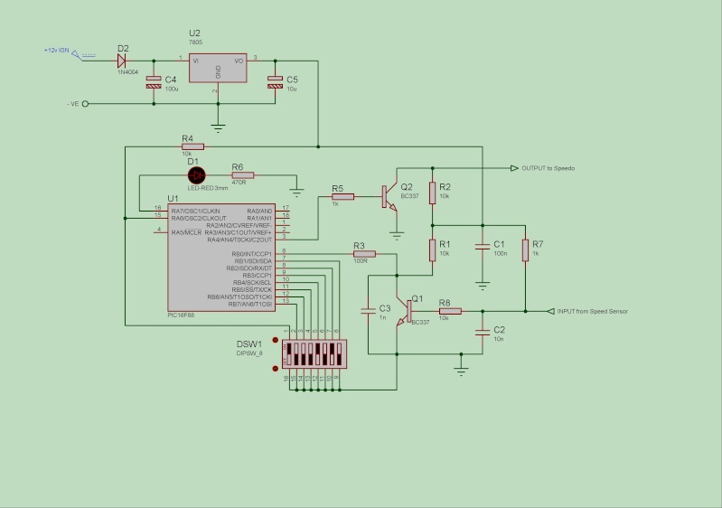
Over the cold dark days of 'Winter' i have been working on a DIY "simple speedo healer" using a PIC 16F88 micro-controller and a handful of discrete components.

The circuit is shown below.......................
Image

Most of the development has been carried out using the Proteus Design software for the circuit so i have the DSN file if you want it and MPLAB for the software.

The code can handle speedo pulses much higher than the bike can produce and therefore reduces linear calculation errors, although nothing can be done with the actual speedo linearity error which is quite bad btw but ok at legal limits.
Error rate of the calculations is less then 1%, which is not bad for a 8-bit processor running at 8Mhz and handling 24 and 32 bit calculations, in lay-man terms, at a true 100mph it could output either 99, 100 or 101.

Percentage calculations are set using the DIP switches in 1% steps with switch 1 (on the diagram) to set faster or slower corrections, the code will handle any correction value up to 100%. It also incorporates some switch settings for testing purposes, a power test, a 400Hz and 1Khz output test and an input test to make sure the signal from the speedo sensor is being received and the LED will be on to show things are working during testing.

I have built a prototype on a piece of 30x40mm matrix board and tested it on the workbench using a Honda speedo and a Yamaha R6 unit and it works as expected, i also re-programmed the odo readings whilst i was playing as with any healer, the recorded mileage calcuations can't be changed. The Firestorm speed sensor outputs a signal 14.57 times a second for every 1mph its travelling and uses this to record the covered miles, changing sprockets alters speed but not the recorded mileage.

So, if anyone is interested in having a go at building one, let me know and i will let you have the HEX file for the PIC.

Would also appreciate any feedback on the circuit.

Cheers
Last edited by Phil-VTwin on Sun Mar 21, 2010 9:22 pm, edited 2 times in total.
Ride Safe
Phil
User avatar
Pete.L
Forum Health And Safety Officer
Posts: 7208
Joined: Fri Sep 26, 2003 5:09 pm
Location: Bristol

Re: DIY Speedo Healer (electronics knowledge required)

Post by Pete.L »

Looks good Phil,
Made me laugh to see a good old BC337 put into use still. :thumbup:
My only criticism would be to show the input from the 12v supply on the bike and to add the 5 v regulator. If you also produced a little kit list with some pt.nos and instructions I'm sure there might be some taker on here who might want to have a go at building their own and installing it. :thumbup:
Great idea Phil :clap:

Pete.l
My new ride is a bit of a Howler and I love to make her Squeal
User avatar
Phil-VTwin
Posts: 348
Joined: Mon May 11, 2009 11:21 am
Location: Olney, Bucks

Re: DIY Speedo Healer (electronics knowledge required)

Post by Phil-VTwin »

I have updated the diagram in the first post to show a basic 12v to 5v regulator, total current for the circuit is very low <5ma so a heatsink is optional...

Bill Of Materials
=================
Design: D:\Projects\Simple Speedo corrector\SimpleSpeedoV2.DSN
Doc. no.: <NONE>
Revision: <NONE>
Author: <NONE>
Created: 19/11/09
Modified: 02/02/10

QTY PART-REFS VALUE CODE
--- --------- ----- ----
Resistors
---------
3 R1,R2,R4 10k Maplin M10k
1 R3 100R Maplin M100R
2 R5,R8 1k Maplin M1k
1 R6 470R Maplin M470R

Capacitors
----------
1 C1 100n Maplin RA49D
1 C2 10n Maplin RA44X
1 C3 1n Maplin RA39N
1 C4 100u Maplin VH13P
1 C5 10u Maplin VH06G

Integrated Circuits
-------------------
1 U1 PIC16F88
1 U2 7805 Maplin QL31J

Transistors
-----------
2 Q1,Q2 BC337 Maplin QB68Y

Diodes
------
1 D1 LED-RED 3mm Maplin WL32K
1 D2 1N4004 Maplin QL76H

Miscellaneous
-------------
1 DSW1 DIPSW_8 Maplin QY70M


The good old BC337 is probably in everyone's component box which is why i used it but any NPN switching transistor can be used e.g. 2N2222a, resistors are 0.6w metal film

Unfortunately Maplin do not do the PIC 16F88 so try Farnell or RS Components, if you cant get the F88, a 16F87 may be used instead but let me know as i need to supply a different HEX file.

If you don't have access to a PIC programmer, you can send me the chip and i will program it for you (include return postage).

If you do decide to build this project, use a IC socket just in case there is code problem and it needs to be re-programmed.

Probably now a good time to say using this circuit is your own responsibility.

Cheers
Ride Safe
Phil
User avatar
Phil-VTwin
Posts: 348
Joined: Mon May 11, 2009 11:21 am
Location: Olney, Bucks

Re: DIY Speedo Healer (electronics knowledge required)

Post by Phil-VTwin »

Timbo wrote: As i dont see a pot, i am guessing the calibration is done via the DIL switch?

Yes that's correct, the correction value is set using binary but the numbers on the switch are confusing as they don't correspond to binary bits....

e.g.
switch number .....12345678
.......................10001010 is the setting for 10% faster where 1 = on
.......................00001010 is 10% slower

bit 8 or switch pin 1 is the faster/slower setting, the remain 7 bits set the value

All switches on enters test mode to confirm the circuit has power and the code is running, the led will flash.

11111110 is approx a 400Hz test signal = 30mph on the Storm
11111101 is approx a 1Khz test signal = 70mph on the Storm
11111100 is speed sensor test, rotating the rear wheel by hand will pulse the LED if a signal is received.

Cheers
Ride Safe
Phil
User avatar
Phil-VTwin
Posts: 348
Joined: Mon May 11, 2009 11:21 am
Location: Olney, Bucks

Re: DIY Speedo Healer (electronics knowledge required)

Post by Phil-VTwin »

I managed to fit my prototype onto a 40x30mm matrix board, it didn't include the regulator as the R6 unit (which i want to fit on the storm) already has one built in. So i am guessing a 40x40 board will be enough for it all.

Have a look here http://www.expresspcb.com/ for a free PCB design program, i use this to design the board then laser print it to inkjet photo paper, transfer the image to a copper board with an iron and then etch :)

Cheers
Ride Safe
Phil
User avatar
Phil-VTwin
Posts: 348
Joined: Mon May 11, 2009 11:21 am
Location: Olney, Bucks

Re: DIY Speedo Healer (electronics knowledge required)

Post by Phil-VTwin »

Would have liked to fit the cluster from a SP but couldn't afford one, the R6 one was cheap (£25) from eblag and has good size digital speedo readout so i dont have to struggle to see what speed i am doing! (old age, eyesight going downhill :( )

Would be interested to know what board size you get using vero, i used this stuff http://cgi.ebay.co.uk/ws/eBayISAPI.dll? ... 0408193900 and linked it together with kynar wire.
Ride Safe
Phil
User avatar
sirch345
Site Admin
Posts: 21658
Joined: Mon Aug 25, 2003 10:35 pm
Location: The West Country.

Re: DIY Speedo Healer (electronics knowledge required)

Post by sirch345 »

Keep up the good work guy's :D

This sort of thing interests me, although I know very little about it,

Chris.
User avatar
Pete.L
Forum Health And Safety Officer
Posts: 7208
Joined: Fri Sep 26, 2003 5:09 pm
Location: Bristol

Re: DIY Speedo Healer (electronics knowledge required)

Post by Pete.L »

:clap: Nicely Done Phil :clap:
That's more than good enough for someone to make a copy :thumbup:

Pete.l
My new ride is a bit of a Howler and I love to make her Squeal
User avatar
Phil-VTwin
Posts: 348
Joined: Mon May 11, 2009 11:21 am
Location: Olney, Bucks

Re: DIY Speedo Healer (electronics knowledge required)

Post by Phil-VTwin »

Just an update, you dont need 0.6 watt metal film, 0.25 watt carbons will do.

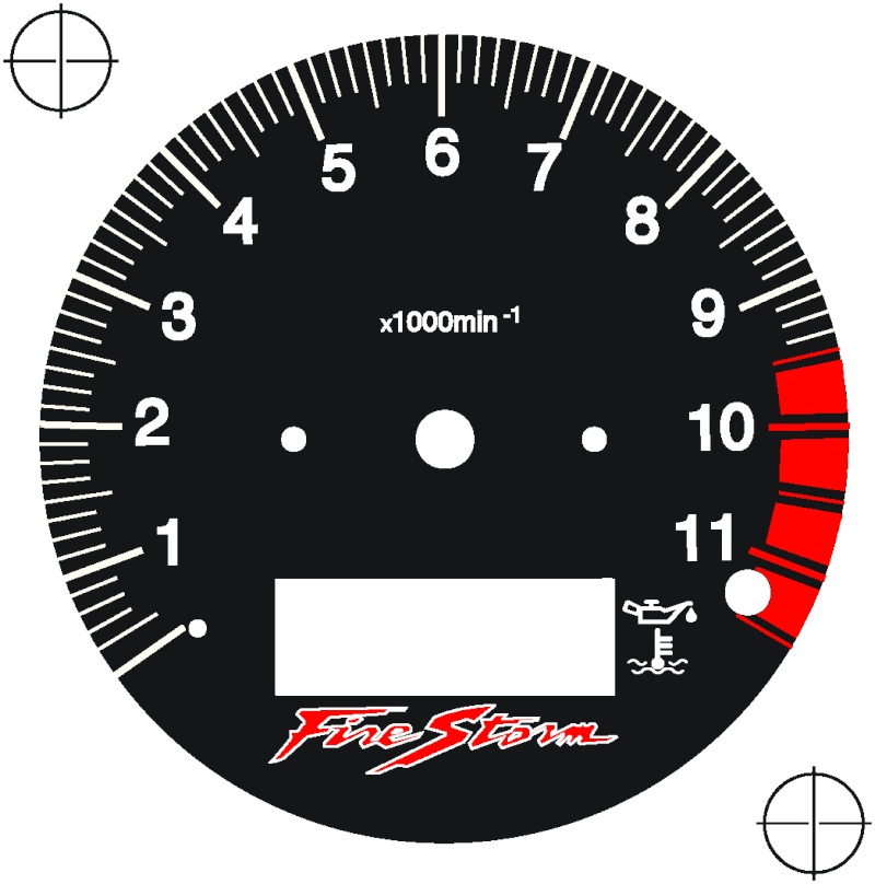
I have created a new guage for the R6 cluster, what do you think?

Image


JPG looks crap but it is nice and crisp in Illustrator and when printed!
Ride Safe
Phil
User avatar
sirch345
Site Admin
Posts: 21658
Joined: Mon Aug 25, 2003 10:35 pm
Location: The West Country.

Re: DIY Speedo Healer (electronics knowledge required)

Post by sirch345 »

Neat job Phil, I like the Firestorm logo you've added :thumbup:

Chris.
User avatar
Phil-VTwin
Posts: 348
Joined: Mon May 11, 2009 11:21 am
Location: Olney, Bucks

Re: DIY Speedo Healer (electronics knowledge required)

Post by Phil-VTwin »

Well i guess no one has tried making this because of.....
A: i have not been asked for the program code.
B: the bloody thing wont work on a Storm as i forgot to add a pull-up resistor on the input!

Anyway diagram updated :lol:
Ride Safe
Phil
User avatar
benny hedges
Posts: 6110
Joined: Sun Oct 18, 2009 5:09 pm
Location: Warrington

Re: DIY Speedo Healer (electronics knowledge required)

Post by benny hedges »

has anyone looked with a satnav at what their speedo is doing - with a 14tooth front sprocket???

going through m6 roadworks i was reading bob on 50 at indicated 50, so went home and stuck my tomtom on.
at 50 it was spot on, at 100 the satnav read 98...
110 it read 107.
that's accurate enough for me tbh - more accurate than me vw.
when you think about it, if the speed is read off the output shaft, it still turns at the same rate/rpm as before, but with the smaller cog i'm going slower which must counteract the inaccuracy of the speedo.
You do not have to say anything. But it may harm your defence if you do not mention when posting something which you later rely on in quote. Anything you do say may be ripped to sh*t.
User avatar
sirch345
Site Admin
Posts: 21658
Joined: Mon Aug 25, 2003 10:35 pm
Location: The West Country.

Re: DIY Speedo Healer (electronics knowledge required)

Post by sirch345 »

benny hedges wrote:has anyone looked with a satnav at what their speedo is doing - with a 14tooth front sprocket???

going through m6 roadworks i was reading bob on 50 at indicated 50, so went home and stuck my tomtom on.
at 50 it was spot on, at 100 the satnav read 98...
110 it read 107.
that's accurate enough for me tbh - more accurate than me vw.
when you think about it, if the speed is read off the output shaft, it still turns at the same rate/rpm as before, but with the smaller cog i'm going slower which must counteract the inaccuracy of the speedo.
BH, are you really running a 14 tooth front sprocket :?: Or do you mean a 15 tooth, remembering standard is a 16 tooth.

Chris.
User avatar
benny hedges
Posts: 6110
Joined: Sun Oct 18, 2009 5:09 pm
Location: Warrington

Re: DIY Speedo Healer (electronics knowledge required)

Post by benny hedges »

14 atm lol - great fun trying to keep the wheel down :mrgreen:
got a 14, 15 & 17 from intobikes.co.uk - top quality and cheapest place in uk, £4 delivery next day.
with the 15 i was still struggling in town traffic at crawling speed in 1st.
don't understand how the speedo picks up tbh cos i would expect the opposite of what i see, as in if the output shaft is spinning at a certain rpm, my bike is now going slower...
but for it to make up the inacuracy of the speedo, i thought i would have had to fit the 17 :confused

crouton it anyway lol - works great and is Very good fun to ride!!
(if not a bit hairy coming out bends wot)
You do not have to say anything. But it may harm your defence if you do not mention when posting something which you later rely on in quote. Anything you do say may be ripped to sh*t.
User avatar
sirch345
Site Admin
Posts: 21658
Joined: Mon Aug 25, 2003 10:35 pm
Location: The West Country.

Re: DIY Speedo Healer (electronics knowledge required)

Post by sirch345 »

WOW :!: so it is a 14 tooth front sprocket after all :thumbup:
I can only imagine it is a bit on the lively side :D

I too find that strange about the speedo readings, but you can't argue with the Sat Nav can you.

A mate of mine who also has a Firestorm tried a bigger rear sprocket. He was expecting the rev's to be showing higher at the same speeds with the lower gearing, but they didn't they were still showing the same, sooooo.... :wtf:

Chris.
Post Reply