Ok, so I took this idea straight from one of David Vizards books and I have to say it works quite well. There are some adjustments to be made but the principal works soundly.
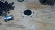
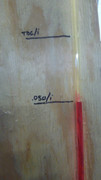
I took the manometer I made for balancing carbs and connected one hose to the spark plug hole with a barbed brass fitting. On the underside of the bench I connected my shop vac with a big fitting that neck up to the piston sized hole. Once you bolt the head down you turn on the vacuum and it pulls a column of fluid down based on the pressure differential between atmosphere and the combustion chamber. After that you advance the cam incrementally and note along the way the pressure drop as you go. I noted a very big drop at .050 and continually greater drop until about .270" of lift. After that there is little to be gained even at full lift. the next series of improvements I need to make are improving the seal around the head and getting a tool to depress the valves precisely without the cam in place. Also, I use ATF in the tube to make it easy to see, I need to figure out if I can convert my pressure drop to Hg".
Just to clarify< all I'm really trying to do with the bench is get a sense of how the heads flow stock and how they flow with minor modifications to valve size and port shape. But, and I think this is more important, I can also measure the flow at each .010" of lift or so to get a better sense of how cam timing, which I'll be balls deep in for the next motor, will make the motor behave.I'm hoping to get as much flow for as little lift and duration as possible so that I can run the lease amount of spring pressure with the lightest valve train possible. The person that ported my other set of heads gave me a few pointers on porting at home that simplify the process tremendously and remove a lot of the voodoo that we all here about. Anyway, a few more tweaks and I can plot some data.
Repeatability is key so I went back at it again today with the same results. With each .010" of lift there is about 1/2" of pressure drop with max lift around .300". However from .270" onward there is very little change in pressure on a stock head with stock valve sizes and stock cams which leads me to believe that the max usable lift on a VTR for flow is about .300". After that any more lift is being used to add duration and or slow the ramp speeds. Considering that information it seems as though there is little to be gained (for street riding) with a set of very expensive cams. If you take a peak at the chart I posted for known cam specs you can look at an OEM cam and compare it to a Moriwaki Stg 1 cam and see that if you advance the OEM intake cam 3 degrees you will be very close to a Mori 1 in terms of opening and closing events, and not too far off with lift and duration. IMHO, if I were to build another motor (which I am) I would not likely use an after market cam unless I had a bunch of money laying around to burn. I will have a set of sprockets slotted and I will focus on timing events instead while using my saved cash to buy a set of JE's.
I'm doing what I can in my spare time to make some sense of this ole gal. Anyway, one of the things we are confronted with is the desire for more power...obviously, but how to do so is not so obvious. To start with we know that we make about 100 Hp and 65 LbFt with a halfway decent tune. We know that the tq peaks around 7400 and the Hp peaks around 8500 and the limiter kicks in at 9500. Without work to the motor being done there is almost no way to improve the torque number (realistically) as it is a measure of mechanical leverage. We really need to have either a bigger bore, longer stroke, higher compression, improved VE, Nitrous, or forced induction.
I know that many people make serious HP claims with regard to whichever mods are done, however, from one dyno to the next, or even from change in weather conditions we can see tremendous HP changes. Even changing fuel over to MR12 or something similar will yield different results just as valve adjustments and cam timing (due to chain stretch) and differing break in procedures will. So for the sake of clarity, let's all remember that the dyno numbers are not the end all be all. The Tq numbers are important for sure, but so is noise level, drivability, mileage, reliability etc. And let's not forget; track use vs street use.
Anyway, back to the issues at hand of making more power. According to Roger the Storm made 125 ish HP in mild race trim, that seems reasonable and it puts the hawk over the 100HP/L ratio and is quite impressive. However, as it sits in stock form the V is a bit lazy and is helped tremendously by using a lighter flywheel, cans, and a filter along with a bit of jetting and a TPS adjust. From that, we might see 105 Hp and about the same Tq numbers albeit it revs more freely and the peak power numbers are a bit higher in the rev range which it approaches much more quickly especially with a larger rear sprocket so that we can use that torque a bit more effectively.
On to the cams...The cams are fairly pricey and a right pain in the ass to change on this bike. I'd rather not do it but I am possessed with the need to tinker, I can't help it. On with it, what we are doing when we use different cams is moving around the timing events so that the power is moved around the rev range differently and that's about all. That has a tremendous effect on how we perceive that power generation but, it does not really add much unless we change the duration and or lift along with it. Why is that...? Because when we change the cam profiles we alter the VE of the engine and potentially increase compression as a result of better filling or reduced pumping losses. But we can only go so much and usually only in one way, i.e. bottom end vs top end. After a certain point the characteristics of the cam no longer match the characteristic of the engine or driving style and it becomes a worthless pile of dung to ride. Either way, I think we can all agree that we want more power upstairs kind of like an inline 4, but we don't want to lose that beast like torque. No problem...
At redline the mean piston speed of the V is at about 4000 ft per min. Not too bad, at 10k its at about 4300, also not too bad, we are well within the mechanical limits of the engine at full throttle in every gear even at redline barring any mechanical issues that are heretofore unknown. So, rev it higher...but don't bother if it's not making any power where you're revving it. Solution, retard the intake cams a few degrees and the power band will climb a little higher. A 4 degree retard will move peak power about 400 rpm higher, the inverse is true too. The same is achieved with a reground cam for the exact same reason only in our situation we need a slotted cam sprocket to do so whereas a cam grinder just grinds it in...for a nice stack of cash. Slotted sprockets--$100.00, cams...$800.00 ish.
I think you're on the money- interesting results regarding cam lift increases giving little extra flow. I guess, once it's open, it's open.
Increasing valve size would also be helpful, but only to a point, because increasing diameter also increases the length of the seal, and the longer the seal, the less sealing efficiency. Also a larger valve head requires more spring pressure to move it and keep the same sealing efficiency, unless you can also move to Ti valves.
The bit that fries my brain is where you get to tuning the exhaust for scavenging efficiency, I can't get over the notion that the least restriction to both inlet path and exhaust path should allow more gas to flow; but it doesn't seem to work that way. That bit is still a dark art to me. I know it's fluid dynamics and trying to achieve a steady stage flow rather than stop:start, which is what the engine produces, but beyond that I run out of facts and knowledge!
The standard cam sprockets are quite hard but not impossible to file, (not sure if you could mill, I suspect you'd break a lot of slot mills getting anywhere).
It's not falling off, it's an upgrade opportunity.
I think you are spot on with the Stop & Start impression of flow. That is exactly what is happening and it's where most people are losing touch with reality. The exhaust leaving and the air coming in have mass and are a column with pressure at the nose and vacuum at the rear. It's because of the stop start motion happening faster than we can really comprehend and the mass associated with that column of air changing direction that we can't really get it right. Especially when you consider how a flow bench works (at steady state) with air at ambient temp and a paltry 28 inches of water. Not to mention that in the case of a bench we flow through the combustion chamber and downward, though in reality nothing of the sort happens. At best we get an approximation of how it will work in real life. I personally think that the bench is best used for determining if a cam is suitable and for getting in the ballpark for porting, beyond that the dyno and real life testing are a must.
As for the gears...There are two distinctly different gears (that I know of) that were made for the VTR by Honda. One is a purely stamped unit and the other is machined. I have both types and I will be having the machined set slotted which is no big deal for any machinist.
tony.mon wrote: ↑Sat Mar 21, 2020 9:29 am
I think you're on the money- interesting results regarding cam lift increases giving little extra flow. I guess, once it's open, it's open.
Increasing valve size would also be helpful, but only to a point, because increasing diameter also increases the length of the seal, and the longer the seal, the less sealing efficiency. Also a larger valve head requires more spring pressure to move it and keep the same sealing efficiency, unless you can also move to Ti valves.
The bit that fries my brain is where you get to tuning the exhaust for scavenging efficiency, I can't get over the notion that the least restriction to both inlet path and exhaust path should allow more gas to flow; but it doesn't seem to work that way. That bit is still a dark art to me. I know it's fluid dynamics and trying to achieve a steady stage flow rather than stop:start, which is what the engine produces, but beyond that I run out of facts and knowledge!
The standard cam sprockets are quite hard but not impossible to file, (not sure if you could mill, I suspect you'd break a lot of slot mills getting anywhere).
Also, regarding the valve diameter, the valves are not the restriction in the V heads, the port cross sections are. After a valve is lifted off the seat about .25~.30D, there is no more available curtain area to pass any intake or exhaust. It can be made more than 100% efficient, but that is where scavenging comes into play in a serious manner but that's not really gonna happen in our application, not with our budgets anyway.
Ace VenTRa wrote: ↑Sat Mar 21, 2020 3:56 pm
And here's the gears:
Zoom in and you'll see the difference.
Bit of 50:50 here but I'm saying the one the right is the machined one. I've not experience of machining but the holes look cleaner cut and the teeth have what look like grooves in them that I'm guessing are from machine tools.
Looks like there are different markings too - two 'o's on one vs two triangles on the other.
The cam info is very interesting, thanks. On the otherhand, damn you. I was going to rebuild my spare engine as stock since cams are hard to find and expensive. But a slotting a set of gears is nowt and the cash for pistons does indeed start to look like not so much of a spend.
It would be interesting use my reground cams for intake and oem in cams for exhaust (they have slightly higher lift) - I even draw some timing for this setup. Price for two cams was good, about 130 pounds in the past, only problem is it is not probably available as of today
You will not gain much just by retiming oem cams, duration and valve lift is still the same. Only benefit is you will correct some flaws in oem timing and have better running engine, but not major gain.
You are correct, however, the ex cams really don't have any more lift. At least not the 3 sets I've measured. They have .405" of lobe lift on both the exhaust and intake. I have not yet verified the timing events yet though. Either way, "gain" is relative, if you move the power to where you more use it, it will be a tremendous gain for you. A wider LSA may be your thing, a bit of advance, a bit of retard...take your pick and give it a go.
Ace VenTRa wrote: ↑Sat Mar 21, 2020 3:56 pm
And here's the gears:
Zoom in and you'll see the difference.
Bit of 50:50 here but I'm saying the one the right is the machined one. I've not experience of machining but the holes look cleaner cut and the teeth have what look like grooves in them that I'm guessing are from machine tools.
Looks like there are different markings too - two 'o's on one vs two triangles on the other.
The cam info is very interesting, thanks. On the otherhand, damn you. I was going to rebuild my spare engine as stock since cams are hard to find and expensive. But a slotting a set of gears is nowt and the cash for pistons does indeed start to look like not so much of a spend.
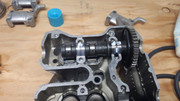
The one on the right is machined, the left is a stamped unit. If you put either one on a cam and check the timing marks there is a distinct difference in alignment. I mention that because when we time a motor we use 6 different timing marks, 2 on the crank and 1 on each cam. Plus the stretch in each chain and wear on the cam sprockets as well as the crank sprockets. Combining all those stacked tolerances leads to big differences from one engine to the next. And that is why we need to use a degree wheel and dial indicator at assembly.