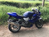
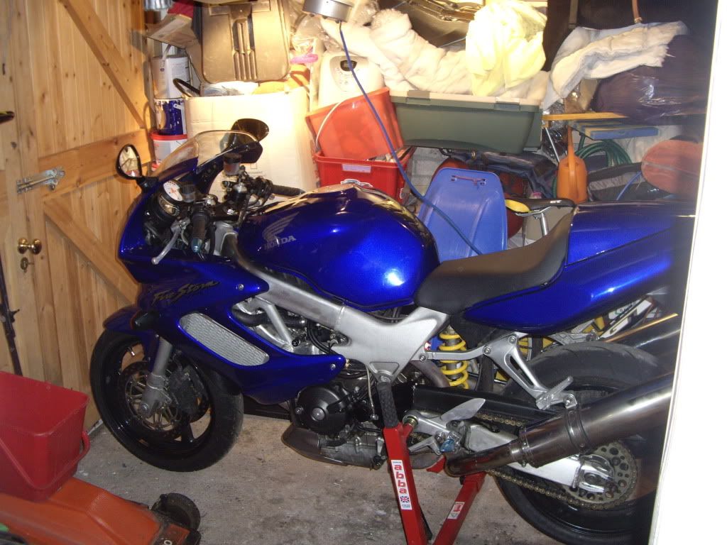
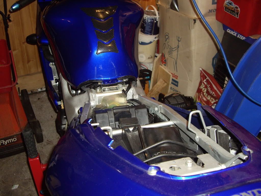
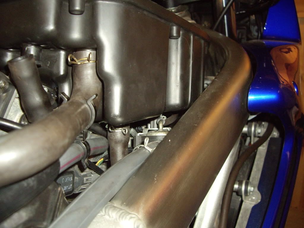
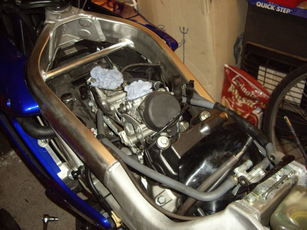
View before work began
Seat removed
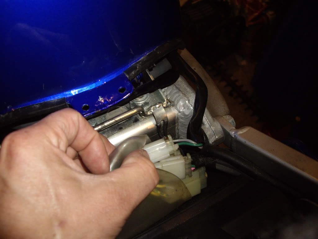
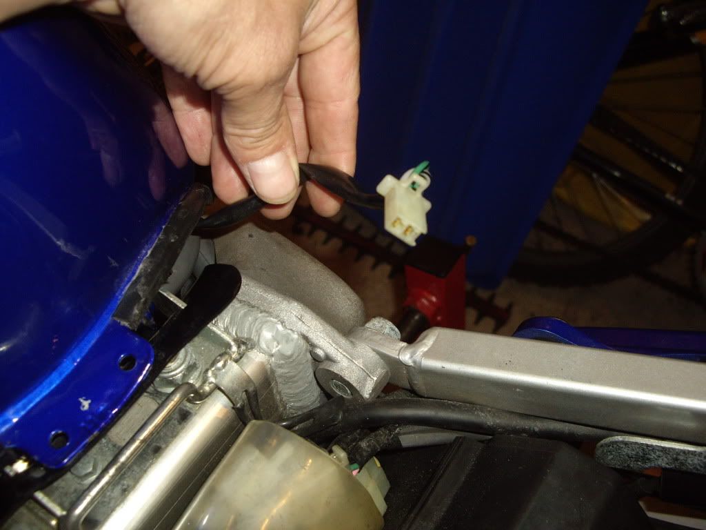
Disconnecting fuel sender unit
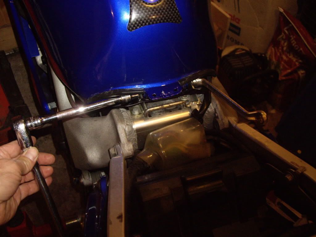
Loosening pivot bolt at the rear of the tank
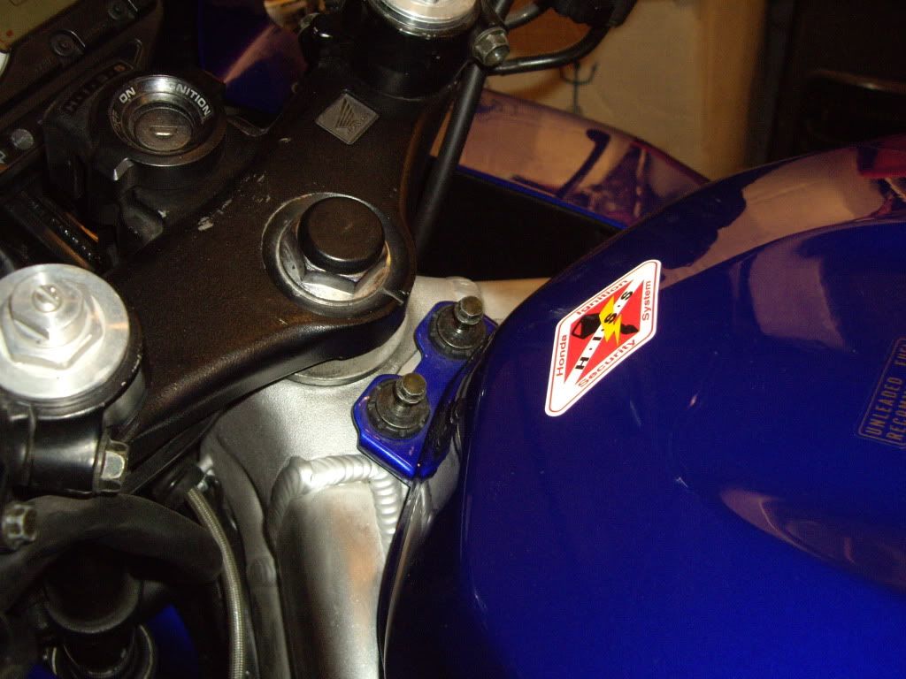
Removing front bolts
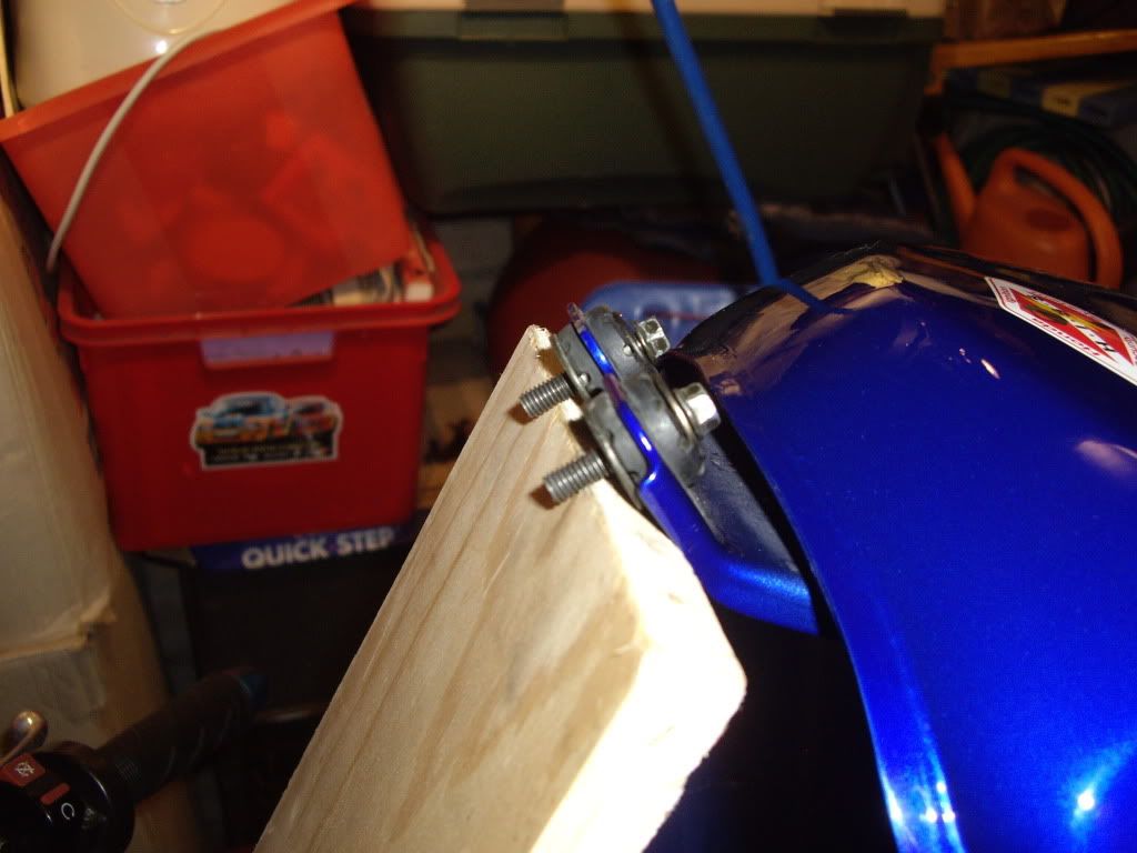
Support the tank using a piece of ply, note I use the tank bolts as added slippage protection
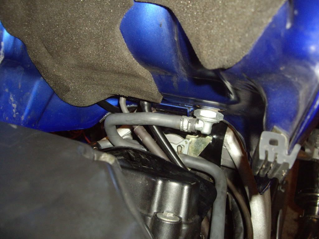
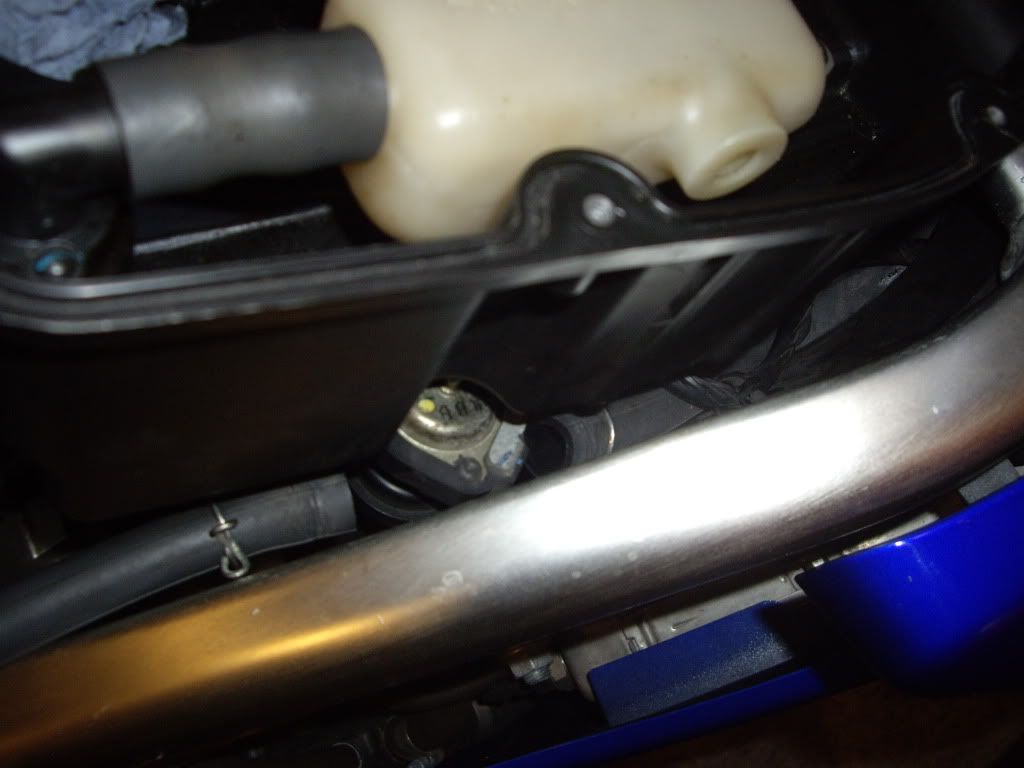
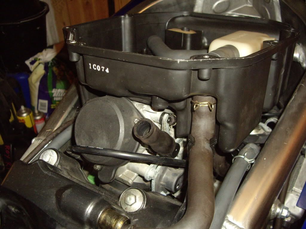
View under the tank note 2002 model and no shutoff valve.
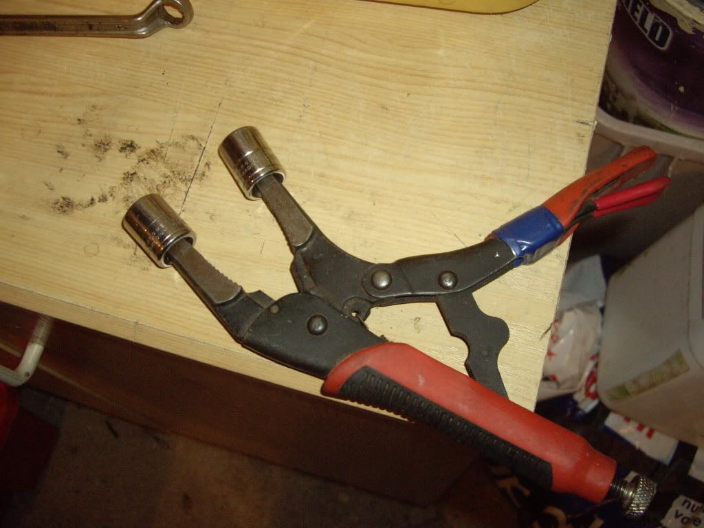
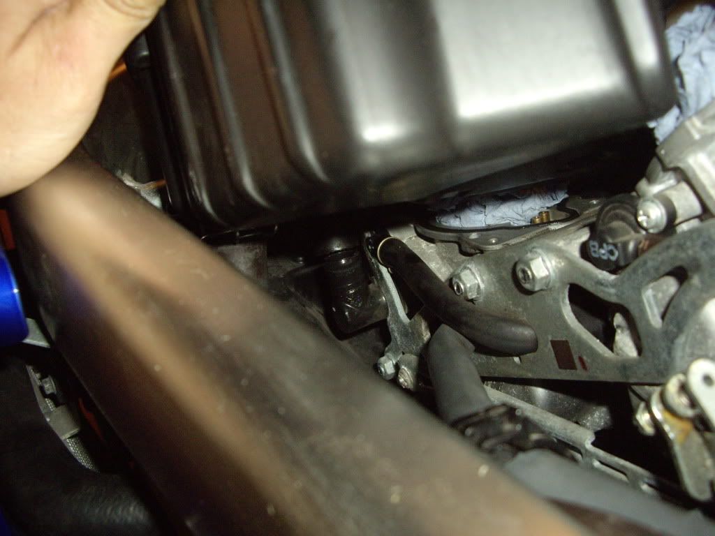
Adapted tool to clamp off the fuel line. Note, have as little fuel as possible in the tank. I had 1 bar on the fuel gauge
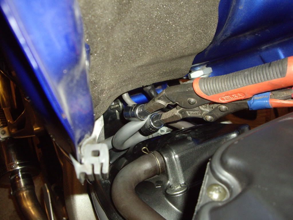
Fuel line clamped off. Note the square rubber tank protector (one on each side) in the foreground of the above photo can fall off, don't loose them.
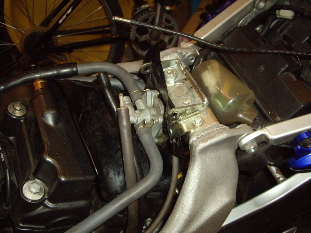
Next follow the main fuel delivery line from the left of the clamping device round to the fuel vacum assembly. Unscrew the fuel line clamp & pull off the fuel hose, there will be a little fuel spillage so have a rag at the ready. Then pull off the vacum & overflow pipes from the bottom of the tank. Those are the 2 pipes still attached to the tank avove the clamping device in the above photo. Note, I have alread removed the nut at the end of the pivot bolt ready for tank removal. Support the tank, remove the pivot bolt , and lift away. Place the tank somewhere safe & I plugged the fuel delivery pipe using a 12mm bolt wrapped with some PTFE tape, this allowed me to remove the clamping device so as not to damage the pipe any further.
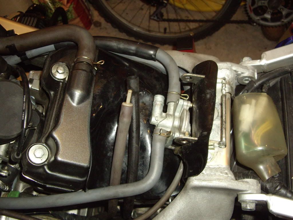
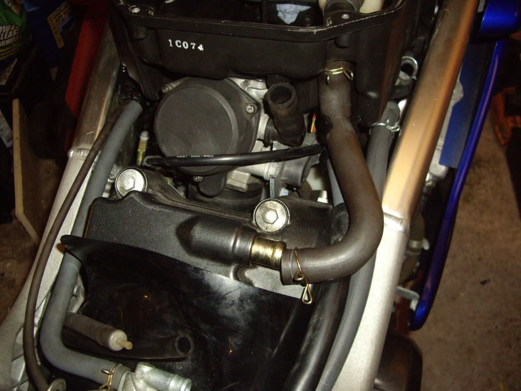
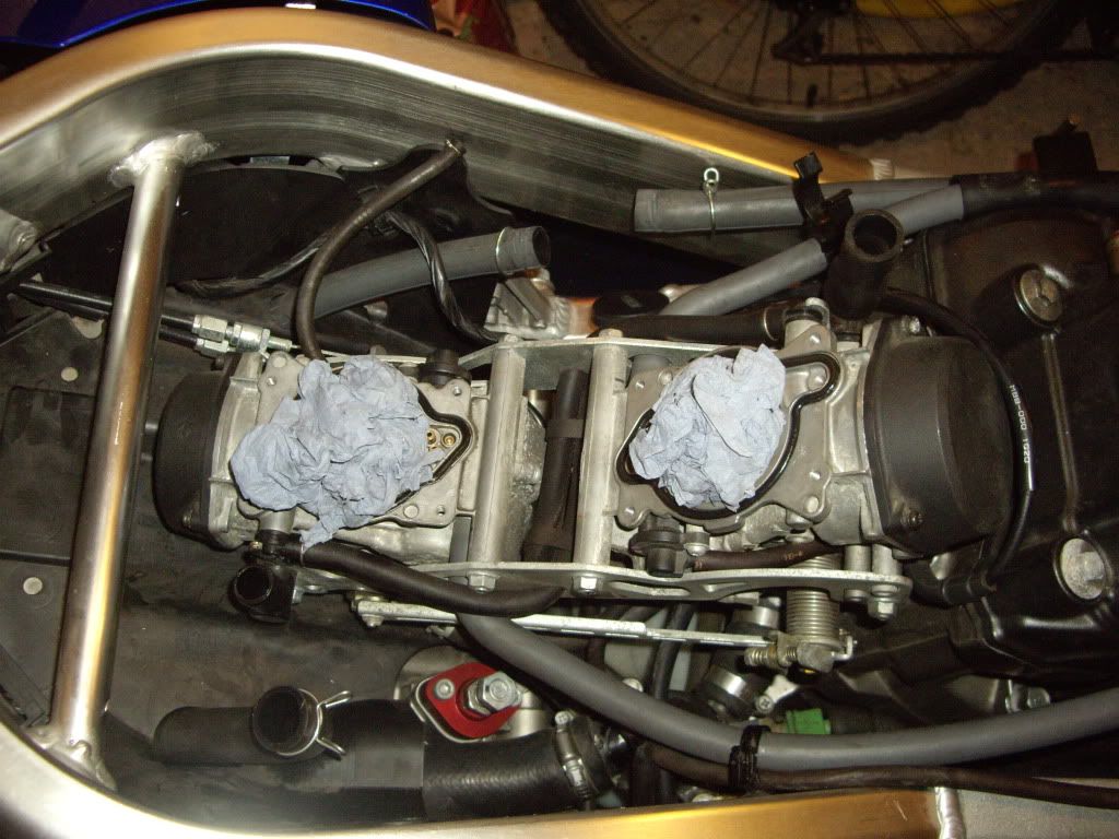
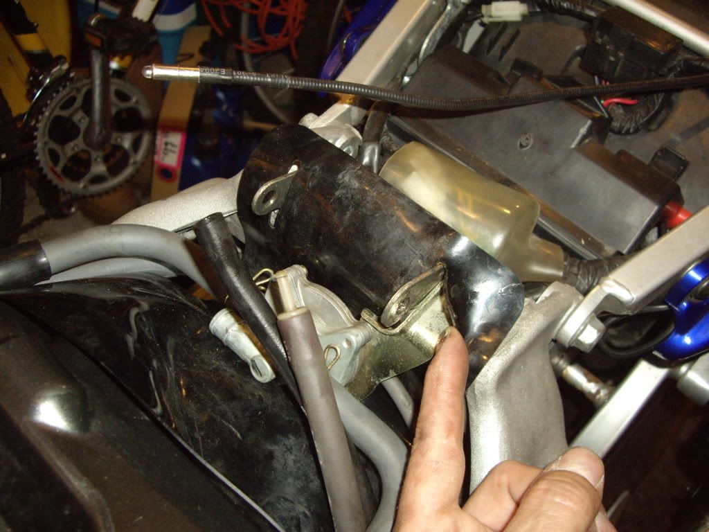
Photo of the tank removed showing the vacum assembly including both main carb fuel feed pipes and the small vacum control pipe.
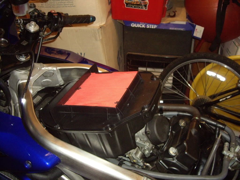
Airbox lid removed showing air filter. Note you can remove this lid & change the air filter without removing the fuel tank by having it pivoted virtically as shown earlier, please have an assistant available to support the tank as you remove the airbox lid just in case.
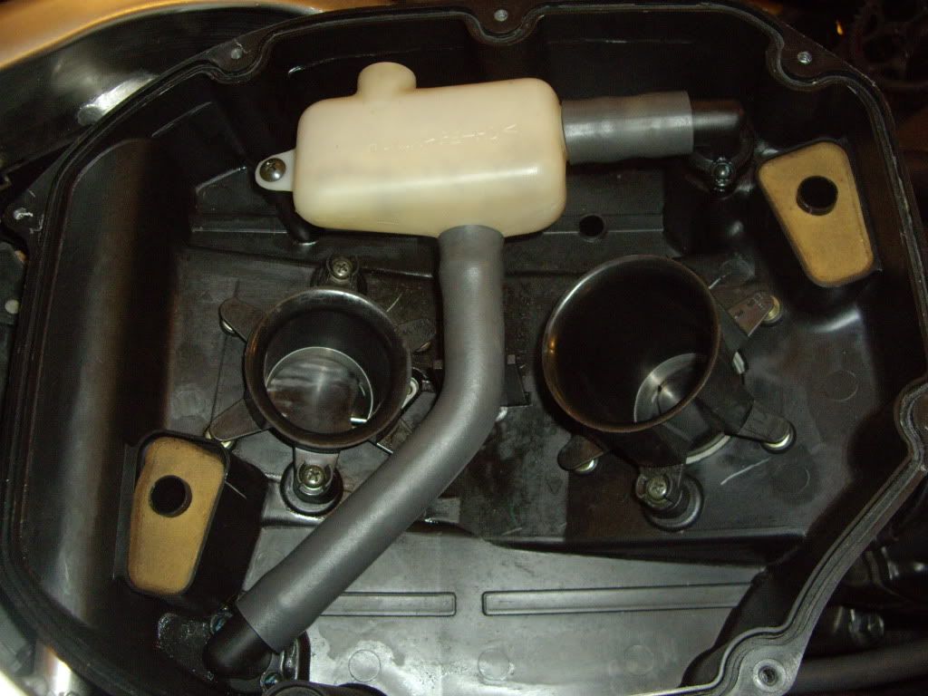
Air filter removed showing trumpets. Note: long trumpet at the rear & small at the front they are arrowed to the airbox housing as to correct orientation.
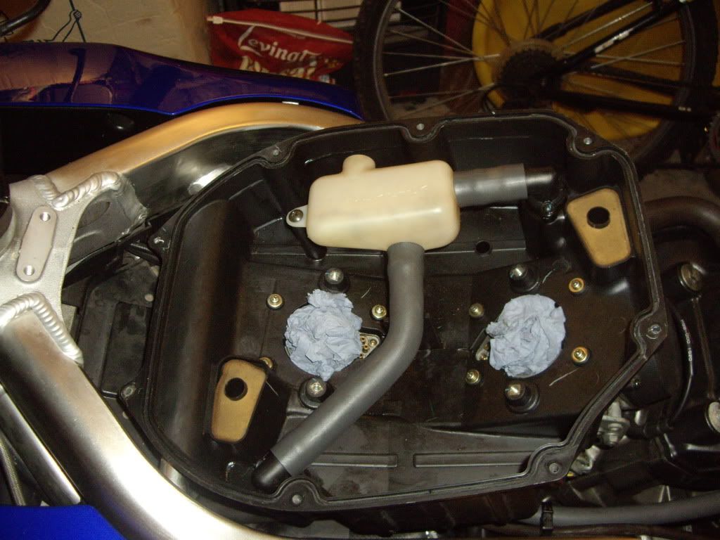
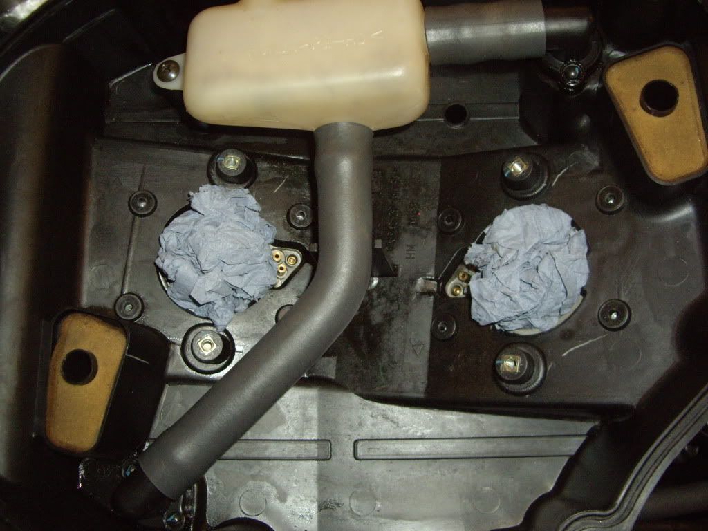
Trumpets removed & carb mouths secured against foreign bodies falling in.
Airbox housing is secured with 8 bolts which are thread locked in. These have now been removed. Now comes the plumping bit. The following are photos of various pipes that need to be removed that can be done in any order. Accessability & small hands are an advantage here.
Finally
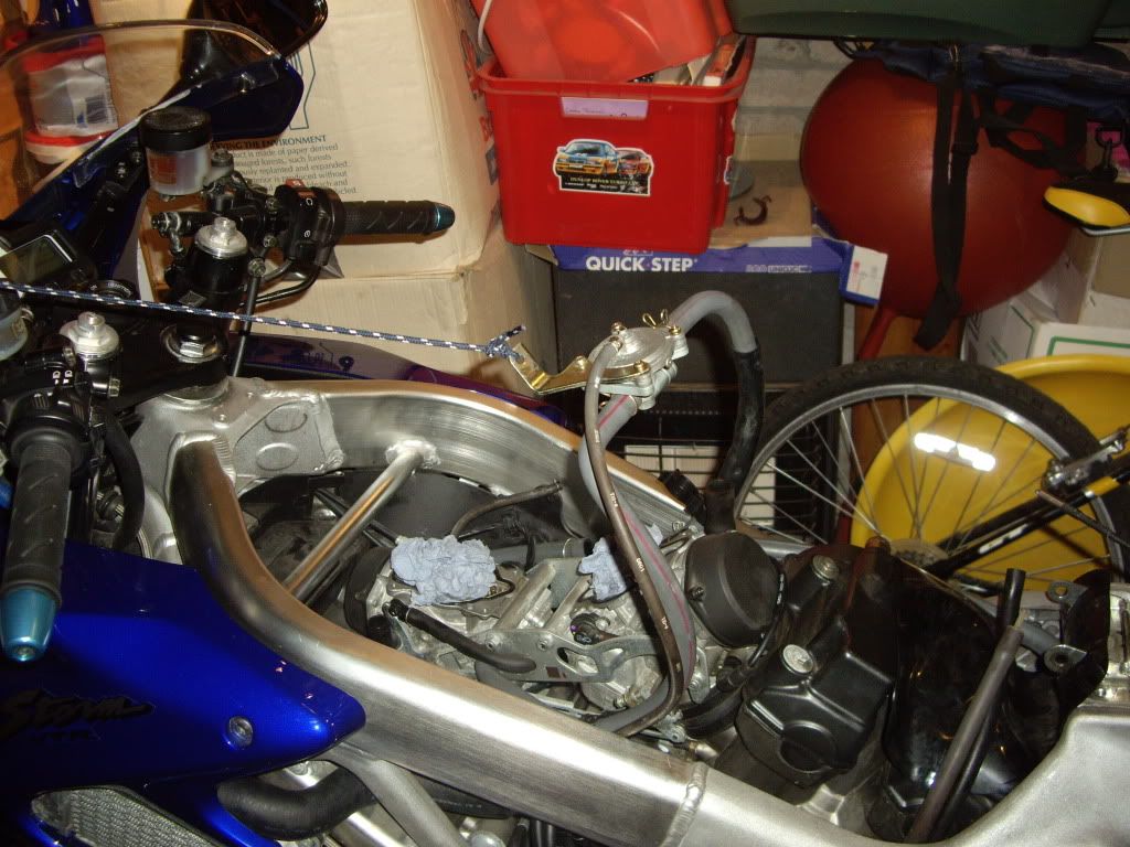
Airbox off. Next up is to remove the fuel vacum assembly
No need to remove all the fuel lines I supported it with a shoe lace attached to the wing mirror
The next sequence of photos is an aid to ensure you remove parts in a particular order so as to repeat in the re-assembly process
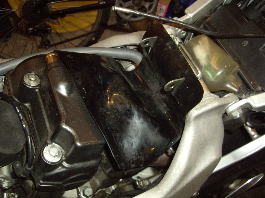
Remove rubber protector
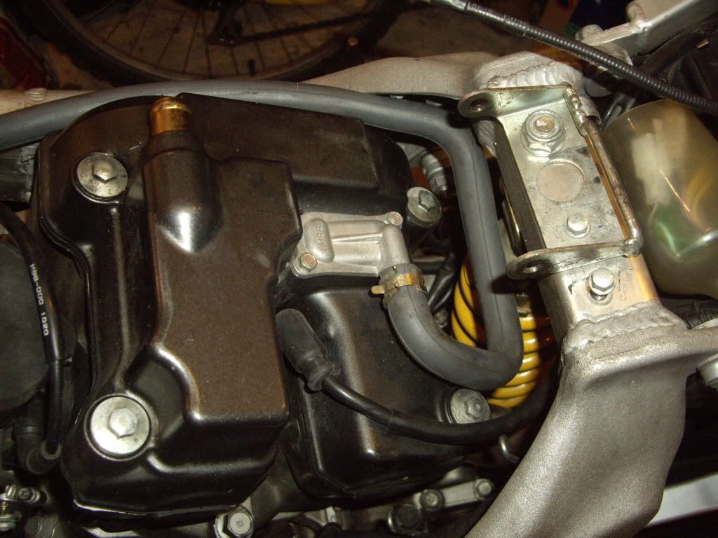
Disconnect & remove rear cylinder pair valve pipe.
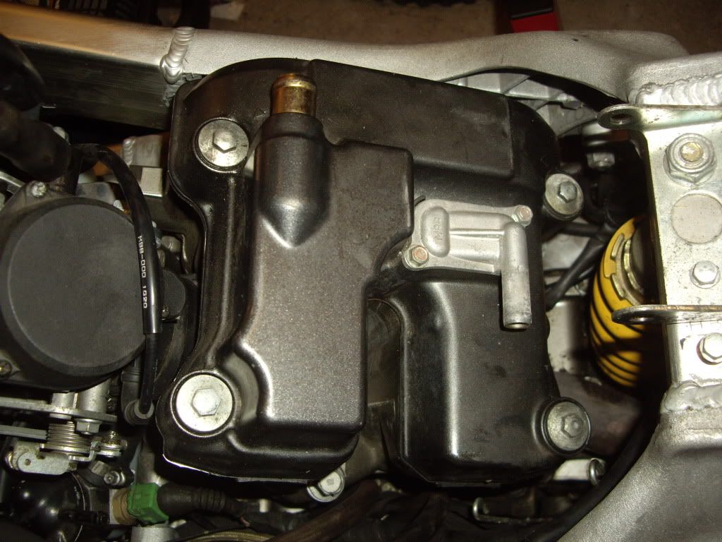
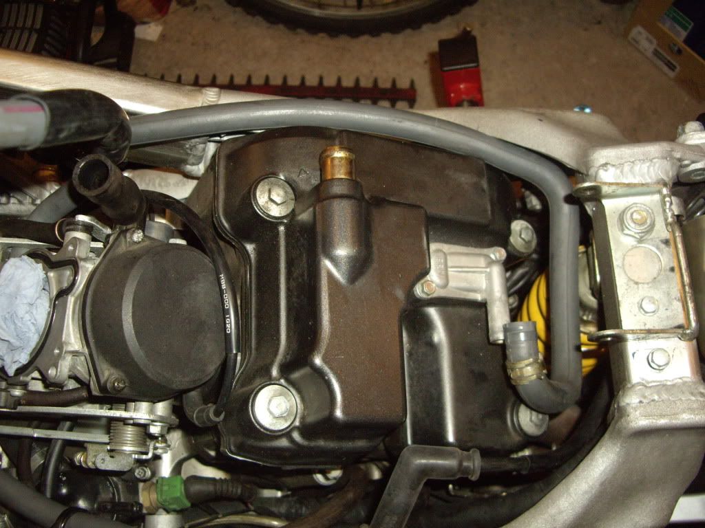
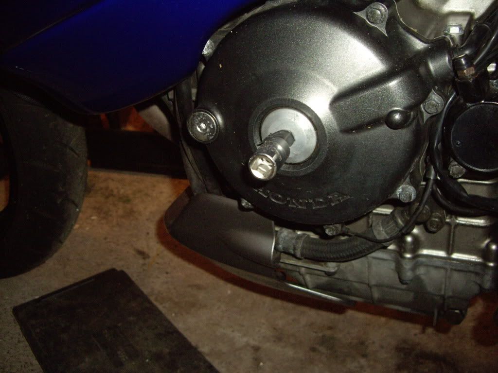
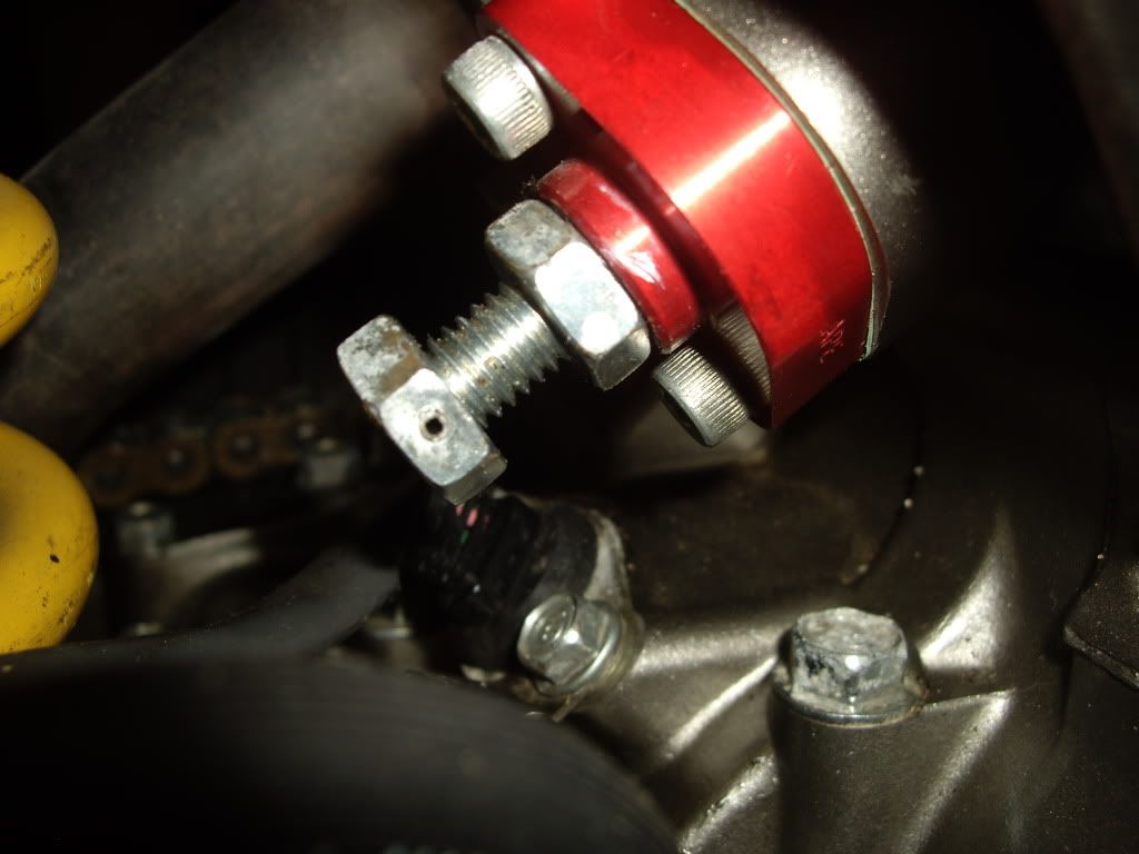
Now you have reached the rear cylinder rocker cover. Before removing first remove the altenator center plug. (AS STATED IN OTHER THREADS THIS IS MADE FROM A VERY SOFT ALLU & CAN BE A SOD
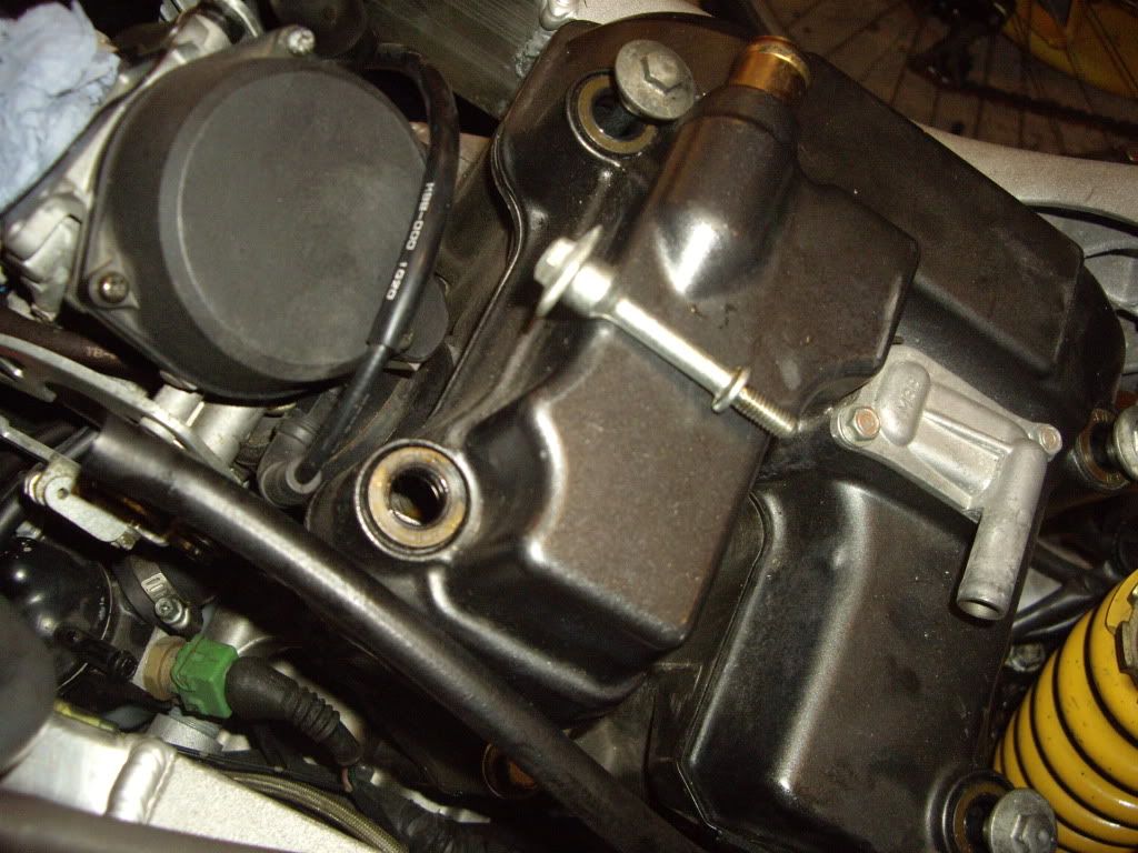
Next remove the 4 rockercover retaining bolts
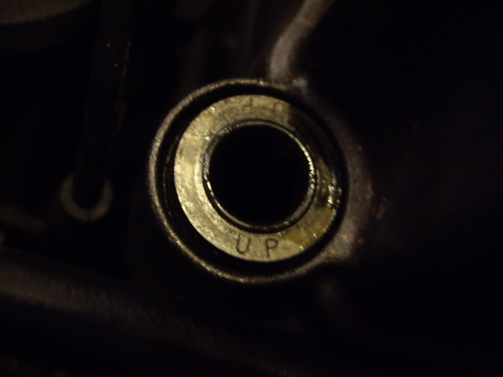
Note: the orientation of the washers the way UP is clearly stated on them. I also smear them with engine oil when replaced.
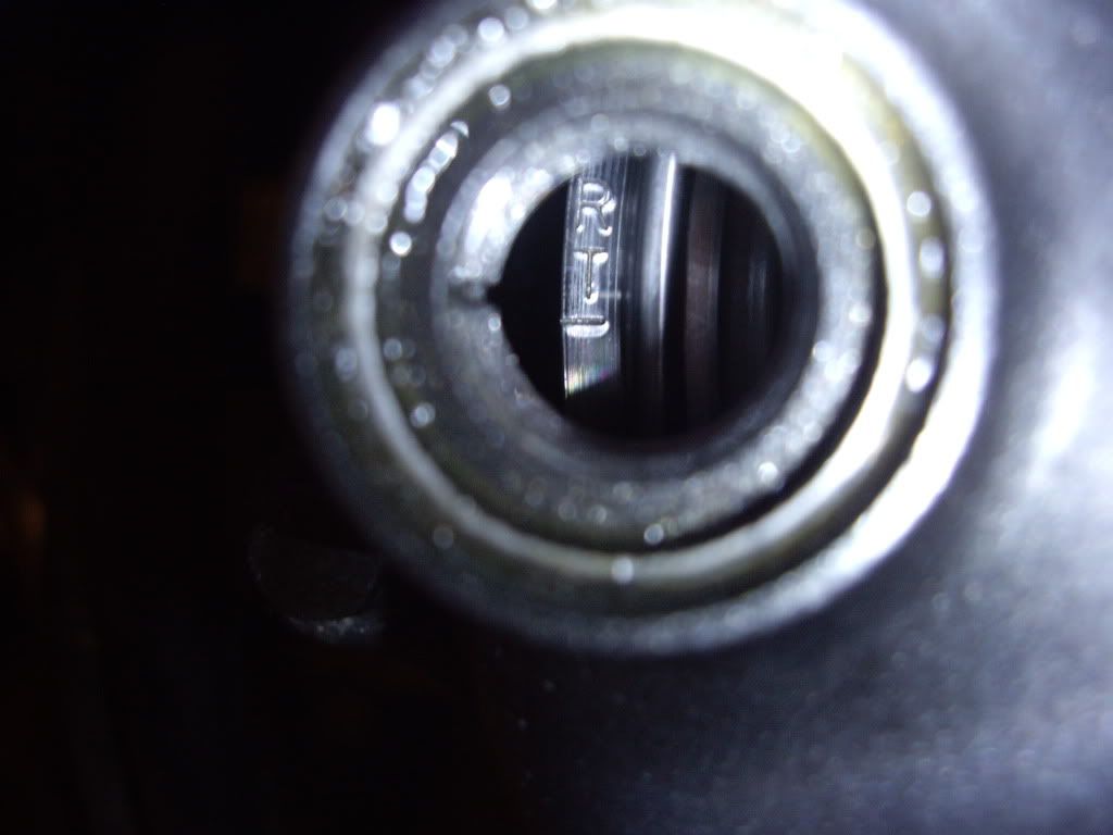
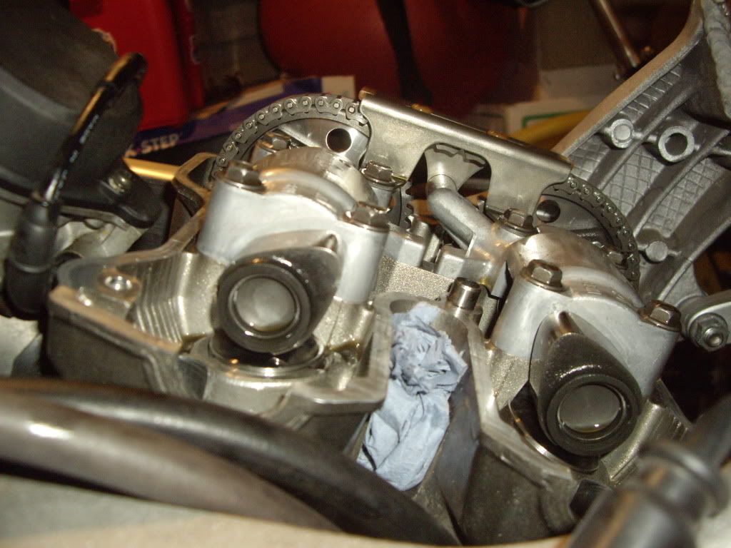
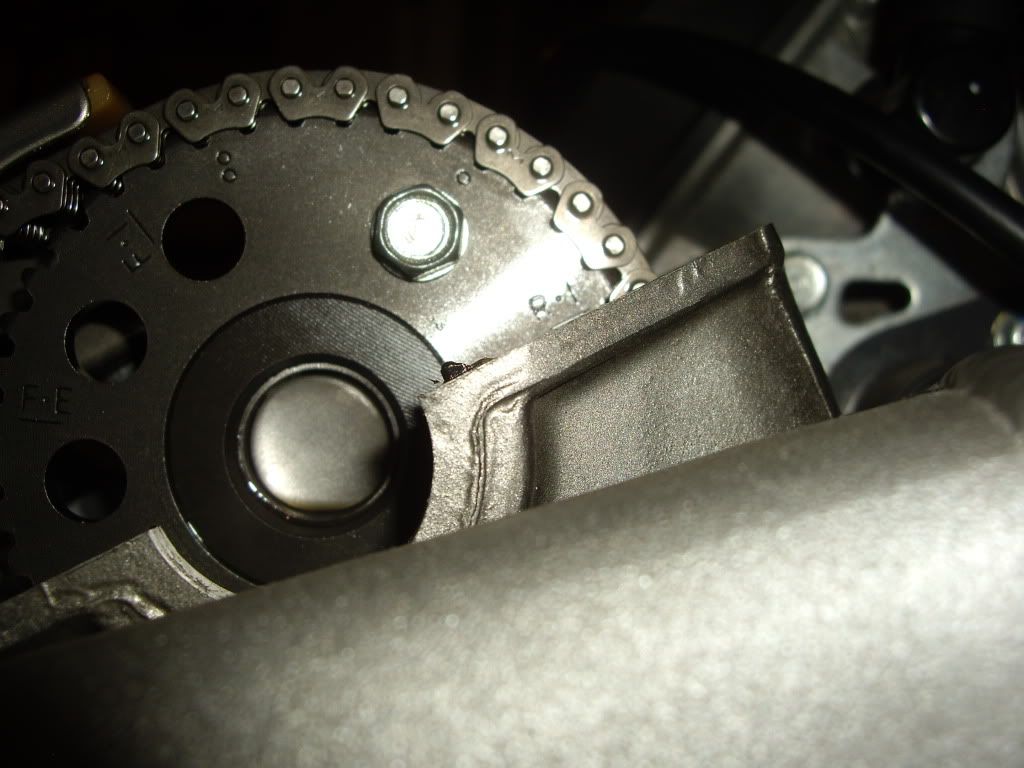
Next you need to find TDC for the REAR cylinder please refer to the CCT thread for this proceedure. Below are photos of what TDC looks like for the REAR cylinder looking at the cam lobes/sprockets & timing window. Note (ALWAYS TURN THE MOTOR COUNTER CLOCKWISE USING A 17MM SOCKET ON THE BOLT IN THE CENTER OF THE ALTENATOR HOUSING).
Reassembly is the reverse of what you have seen. This is as far as I went. My valve clearences are a shade on the tight side but have been reliably informed that they can wait for the the next workshop. I also stopped the leak on my APE CCT.
I hope this will help some of you out there I do like photos as they speak a thousand words. Happy spanners