Ok, I finally had the time to measure these... This is my "drawings" for my adapters... Not complete by any means... Keep in mind this is not scaled... I gave up trying to find a decent Freeware Cad program to transfer my paper outlines/measurements...
So to use this, you need to look at measurements, not the image of the footrest, it's just there for reference... (So, no you can't print it and sketch it off...) I used the pivot bolt as my point of reference and measure it out in a grid... Also, all measurements are in mm, not inches, you get to convert them if you want it any other way... All measurements are +/- .2 mm
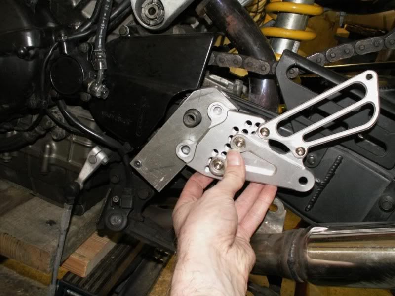
The two bolt holes I measured out, is where I placed the boltholes on my adapters... That placement allowed me to set the footpegs at the OEM position with the adjustable rearsets set "in the middle" of the optional holes... So these apply to my rearsets alone... Again, just for reference...
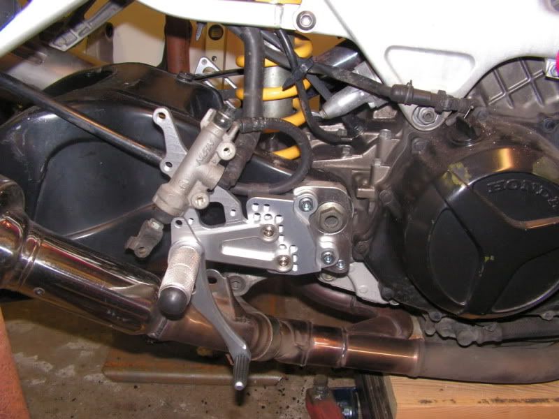
The marking for the OEM placement of the rearset is there... Use that as a point of reference and place the rearset of your choice there, measure out your starting position and your "star" of holes for adjustment... Make sure they don't go inside the rings, that's where you want a big nut, and the material intact...
The vertical reference I used is set to where the stock footpeg has the rubber horisontally... In my case I could ignore that, as I used round alu pegs, but if you are using OEM rearsets from another bike, keep that in mind when aligning stuff...
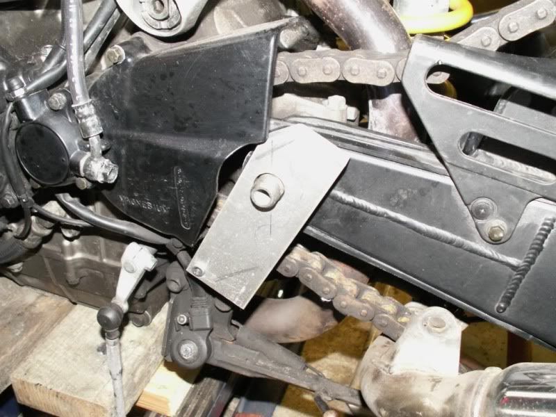
Also, the front outline on the chain side is somewhat important, as it follows the contour of the sprocket guard, not following the outline, makes it impossible to fit the footpeg/adapter...
I simplified mine by making the plate uniformly thick, countersinking the smaller bolts and adjusting the spacer length a bit... If you make a CNC version, you can make it nicer, I included the OEM measurements for reference...

Taken from
http://www.superhawkforum.com/forums/ge ... ers-24563/


