Hi...
I have fitted a acewell digital speedo on my project VTR 99 european model with carbs. Im no expert on wiring etc but have successfully fitted the speedo (magnetic pickup on Wheel) and all features working. I have a problem with the bike which is not happy revving over 4ooorpm. The haynes manual shows the original tachometer is connected to the ignition control unit this wire is now disconnected as its not used with the acewell speedo. The wiring loom has been fully adapted so connecting the old clocks wouldnt be easy to test.
Has anyone any experience of doing something simular? Does the ICU need input from the tachometer?
Any tips welcome before I move on to other possible issues that might be causing the above problem.
Thanks
Swapping speedo etc for a acewell digital speedo !!!!

Re: Swapping speedo etc for a acewell digital speedo !!!!
A lot of people who have fitted a different dash including cbr dashes have had to put a Speedo Healer on to get the rev counter to behave and show accurate readings. Don't know if this is the solution for you but it may be worth investigating.
http://www.vtr1000.org/phpBB3/viewtopic ... sh#p238883
(:-})
http://www.vtr1000.org/phpBB3/viewtopic ... sh#p238883
(:-})
Last edited by VTRDark on Sat Dec 22, 2012 11:36 am, edited 1 time in total.
==============================Enter the Darkside
Re: Swapping speedo etc for a acewell digital speedo !!!!
Was it revving ok before you changed the dash?
And was any other work done at the same time?
And was any other work done at the same time?
It's not falling off, it's an upgrade opportunity.
Re: Swapping speedo etc for a acewell digital speedo !!!!
Hi stew
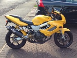
I fitted a Motogadget unit to my fightered Storm (see "Tango'd Storm" in the Pimp My Ride section) a few years ago and remember well the head-scratching...

Firstly, let's just confirm which wire is looking for a new home to go to. I'm assuming its the YELLOW/GREEN that you've isolated? The only other two wires to/from the tacho are a BLACK/BROWN which is your fused feed and a GREEN/BLACK which is your earth.
Assuming it is the YELLOW/GREEN, this does need to go somewhere as it's the signal pickup for the tacho. Well, at least it did with my unit! The Motogadget guys were really helpful and suggested I splice this into the BLACK/YELLOW wire that runs between the ICU and the Converter Unit (both of these are identifiable on the Haynes wiring diagram) to pick up the signal. Can't remember why they suggested it but it certainly works and I've never had any problems with either the Motogadget unit or the bike's performance.
BUT BUT BUT... I'd strongly recommend you speak to the Acewell guys before you reconnect it anywhere!
When I built my VTR streefighter, I changed so much of the wiring I decided to map out the new diagram using MS Powerpoint. I can't uplaod the .ppt file to the forum so I've created a .jpg version which should be below. You'll see how I've connected stuff up from this - just download and you'll be able to zoom it:

Does the Acewell have a low fuel warning light too? If so there's a way you can adapt the Firestorm circuitry to make use of it, as I did with the Motogadget unit.
First, you need to locate the little PCB (printed circuit board) on the back of the tacho unit itself. Remove it but be careful cos it's a bit delicate. What I did was to use one of those little clear plastic cases you find digital tapes in (remember those? The tapes that used to be used with camcorders) - they're about 7cm x 5cm. I cut a couple of small holes in the case to exit the various wires. Note that you'll need to run two new wires from the PCB to the Acewell's warning light as the PCB is wired directly to VTR's tacho and that connection obviously need to be cut at time of removal. So the connections will be:
BROWN/BLACK to the fuel level sensor
BLACK/BROWN to your fused feed
GREEN to earth
Two new connections from the PCB to the Acewell warning light (which may only work one way around if it's an LED)
Again, my attached wiring diagram will show the relevant connections. Once tested and working fine, I padded the tape case with soft foam all around and laid the PCB inside, sealing and protecting the case by wrapping in black insulation tape. Simples... A pic below shows the "black box" located on the front of my bike's airbox:

IMPORTANT!!! Remember, my wiring advice is specifically relevant to the Motogadget unit I fitted, which MAY NOT be identical to the Acewell unit. With wiring, always be sure you're making appropriate modifications to avoid your pride & joy disappearing in a cloud of smoke and flames... Like I said, if you're unsure, speak to Acewell to get their advice or ask a professional who knows his way around multi-coloured spaghetti!
Give me a shout if you need any more advice.
Cheers
Scubadog
I fitted a Motogadget unit to my fightered Storm (see "Tango'd Storm" in the Pimp My Ride section) a few years ago and remember well the head-scratching...
Firstly, let's just confirm which wire is looking for a new home to go to. I'm assuming its the YELLOW/GREEN that you've isolated? The only other two wires to/from the tacho are a BLACK/BROWN which is your fused feed and a GREEN/BLACK which is your earth.
Assuming it is the YELLOW/GREEN, this does need to go somewhere as it's the signal pickup for the tacho. Well, at least it did with my unit! The Motogadget guys were really helpful and suggested I splice this into the BLACK/YELLOW wire that runs between the ICU and the Converter Unit (both of these are identifiable on the Haynes wiring diagram) to pick up the signal. Can't remember why they suggested it but it certainly works and I've never had any problems with either the Motogadget unit or the bike's performance.
BUT BUT BUT... I'd strongly recommend you speak to the Acewell guys before you reconnect it anywhere!
When I built my VTR streefighter, I changed so much of the wiring I decided to map out the new diagram using MS Powerpoint. I can't uplaod the .ppt file to the forum so I've created a .jpg version which should be below. You'll see how I've connected stuff up from this - just download and you'll be able to zoom it:
Does the Acewell have a low fuel warning light too? If so there's a way you can adapt the Firestorm circuitry to make use of it, as I did with the Motogadget unit.
First, you need to locate the little PCB (printed circuit board) on the back of the tacho unit itself. Remove it but be careful cos it's a bit delicate. What I did was to use one of those little clear plastic cases you find digital tapes in (remember those? The tapes that used to be used with camcorders) - they're about 7cm x 5cm. I cut a couple of small holes in the case to exit the various wires. Note that you'll need to run two new wires from the PCB to the Acewell's warning light as the PCB is wired directly to VTR's tacho and that connection obviously need to be cut at time of removal. So the connections will be:
BROWN/BLACK to the fuel level sensor
BLACK/BROWN to your fused feed
GREEN to earth
Two new connections from the PCB to the Acewell warning light (which may only work one way around if it's an LED)
Again, my attached wiring diagram will show the relevant connections. Once tested and working fine, I padded the tape case with soft foam all around and laid the PCB inside, sealing and protecting the case by wrapping in black insulation tape. Simples... A pic below shows the "black box" located on the front of my bike's airbox:
IMPORTANT!!! Remember, my wiring advice is specifically relevant to the Motogadget unit I fitted, which MAY NOT be identical to the Acewell unit. With wiring, always be sure you're making appropriate modifications to avoid your pride & joy disappearing in a cloud of smoke and flames... Like I said, if you're unsure, speak to Acewell to get their advice or ask a professional who knows his way around multi-coloured spaghetti!
Give me a shout if you need any more advice.
Cheers
Scubadog
Re: Swapping speedo etc for a acewell digital speedo !!!!
Nice write up that scubadog and a very impressive wiring diagram. 
It just goes to show the importance of making notes when modding things.
(:-})
It just goes to show the importance of making notes when modding things.
(:-})
==============================Enter the Darkside
Re: Swapping speedo etc for a acewell digital speedo !!!!
That's a good write-up.
Scuba, make that one a sticky in WS K base.

Scuba, make that one a sticky in WS K base.
It's not falling off, it's an upgrade opportunity.
Re: Swapping speedo etc for a acewell digital speedo !!!!
Sorry mate, I can build ahalf decent bike but couldn't "make that one a sticky in WS K base" if my life depended on it... Come again...?
Re: Swapping speedo etc for a acewell digital speedo !!!!
If you edit your thread, you can choose with the option buttons to "make this thread a sticky" which leaves it permanently at the top of the listings.
Ideally this would be in the Workshop Knowledgebase section of the forum.
To do this you might have to copy and paste it to the correct section.
If you have a look at this section (it can be found at the top of the Workshop section) it contains many write-ups worth preserving for other owners to consult and copy/modify/comment on.
Sort of like a library of good ideas.
It's not falling off, it's an upgrade opportunity.
Re: Swapping speedo etc for a acewell digital speedo !!!!
Thanks for your detailed info which Im sure it will help. The tachometer wire is the yellow / green wire. The acewell clock can be connected to this wire or there is the option to wrap the acewell connecting wire around the HT lead which currently works. My main concern was whether the ECU needs a signal to tell it what rev the engine is producing to keep the ignition system working correctly over 3500rpm.scubadog wrote:Hi stew
I fitted a Motogadget unit to my fightered Storm (see "Tango'd Storm" in the Pimp My Ride section) a few years ago and remember well the head-scratching...
Firstly, let's just confirm which wire is looking for a new home to go to. I'm assuming its the YELLOW/GREEN that you've isolated? The only other two wires to/from the tacho are a BLACK/BROWN which is your fused feed and a GREEN/BLACK which is your earth.
Assuming it is the YELLOW/GREEN, this does need to go somewhere as it's the signal pickup for the tacho. Well, at least it did with my unit! The Motogadget guys were really helpful and suggested I splice this into the BLACK/YELLOW wire that runs between the ICU and the Converter Unit (both of these are identifiable on the Haynes wiring diagram) to pick up the signal. Can't remember why they suggested it but it certainly works and I've never had any problems with either the Motogadget unit or the bike's performance.
BUT BUT BUT... I'd strongly recommend you speak to the Acewell guys before you reconnect it anywhere!
When I built my VTR streefighter, I changed so much of the wiring I decided to map out the new diagram using MS Powerpoint. I can't uplaod the .ppt file to the forum so I've created a .jpg version which should be below. You'll see how I've connected stuff up from this - just download and you'll be able to zoom it:
Does the Acewell have a low fuel warning light too? If so there's a way you can adapt the Firestorm circuitry to make use of it, as I did with the Motogadget unit.
First, you need to locate the little PCB (printed circuit board) on the back of the tacho unit itself. Remove it but be careful cos it's a bit delicate. What I did was to use one of those little clear plastic cases you find digital tapes in (remember those? The tapes that used to be used with camcorders) - they're about 7cm x 5cm. I cut a couple of small holes in the case to exit the various wires. Note that you'll need to run two new wires from the PCB to the Acewell's warning light as the PCB is wired directly to VTR's tacho and that connection obviously need to be cut at time of removal. So the connections will be:
BROWN/BLACK to the fuel level sensor
BLACK/BROWN to your fused feed
GREEN to earth
Two new connections from the PCB to the Acewell warning light (which may only work one way around if it's an LED)
Again, my attached wiring diagram will show the relevant connections. Once tested and working fine, I padded the tape case with soft foam all around and laid the PCB inside, sealing and protecting the case by wrapping in black insulation tape. Simples... A pic below shows the "black box" located on the front of my bike's airbox:
IMPORTANT!!! Remember, my wiring advice is specifically relevant to the Motogadget unit I fitted, which MAY NOT be identical to the Acewell unit. With wiring, always be sure you're making appropriate modifications to avoid your pride & joy disappearing in a cloud of smoke and flames... Like I said, if you're unsure, speak to Acewell to get their advice or ask a professional who knows his way around multi-coloured spaghetti!
Give me a shout if you need any more advice.
Cheers
Scubadog
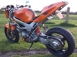
Thanks for the info pleased you replied as your bike offered some inspiration for my project although gone the cafe race road.
Be very interested to know how you got the vfr800 swingarm to accept the t595 wheel / drive etc.
Thanks again
Stew
Re: Swapping speedo etc for a acewell digital speedo !!!!
Thanks for the info have posted reply further down the listing.cybercarl wrote:A lot of people who have fitted a different dash including cbr dashes have had to put a Speedo Healer on to get the rev counter to behave and show accurate readings. Don't know if this is the solution for you but it may be worth investigating.
(:-})
The rev counter currently working and for me accurate enough not to worry me.
The ignition system was top of my list to start with although.....
Bike has a custom 2 into 1 exhaust
Bike has an adapted air box with 2 cone K&N filters
So the carbs will need a dynojet kit for further tuning. I still feel its an ignition problem over fuel at the mo had a similar problem with my hayabusa when I needed a throttle position sensor the engine run lean and no revs over 3000rpm but the bike is obviously injection so relies on many sensors.
Thanks for your help.
Stew
Re: Swapping speedo etc for a acewell digital speedo !!!!
I would worry that the problem with reving is down to the intake airflow. The storm is Very Very Very fussy on how the air is fed in.
Some examples:
1) with the fairing on it gives big problems if you remove teh plastic infill below the intake snorkle
2) Scubadog reported that with teh faring off he had to redirect the intakes to get still less turbulent air.
4) Tony.Mon tried to fit a new type of performance filter with special designs to ensure good laminar flow........it wont rev through
so having cone filters would be my #1 worry if the bike is not running through teh rev range
AMcQ
Re: Swapping speedo etc for a acewell digital speedo !!!!
Hi stew
Just a small correction for you - it's the tacho that picks up the signal from the ICU, not the other way around.
Take a look at the thread "Air filter mod?" - there's some more stuff I posted on mods to the airbox. I remember we did some jet changes at the time I took the snorkel off, and my memory tells me we did in fact downsize the mains so that would stack up with other views expressed above. But remember I said to block the snorkel hole off and cut some holes elsewhere in the airbox lid. Figuring out wher eto cut the holes was good ol' trial and error - you'll see from a photo of my airbox lid (above) where I eventually did the final cuts.
For more info on fitting the VFR800 arm and the Trumper wheel/axle assembly, take a look at the thread "Tango'd Storm" - I posted some detailed info in there some time ago.
Any questions, give me a shout here or PM me.
Cheers
Scooby