The circuit is shown below.......................
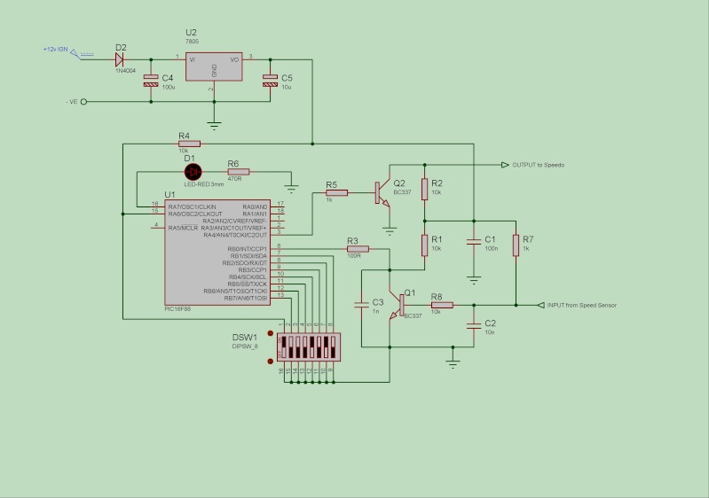
Most of the development has been carried out using the Proteus Design software for the circuit so i have the DSN file if you want it and MPLAB for the software.
The code can handle speedo pulses much higher than the bike can produce and therefore reduces linear calculation errors, although nothing can be done with the actual speedo linearity error which is quite bad btw but ok at legal limits.
Error rate of the calculations is less then 1%, which is not bad for a 8-bit processor running at 8Mhz and handling 24 and 32 bit calculations, in lay-man terms, at a true 100mph it could output either 99, 100 or 101.
Percentage calculations are set using the DIP switches in 1% steps with switch 1 (on the diagram) to set faster or slower corrections, the code will handle any correction value up to 100%. It also incorporates some switch settings for testing purposes, a power test, a 400Hz and 1Khz output test and an input test to make sure the signal from the speedo sensor is being received and the LED will be on to show things are working during testing.
I have built a prototype on a piece of 30x40mm matrix board and tested it on the workbench using a Honda speedo and a Yamaha R6 unit and it works as expected, i also re-programmed the odo readings whilst i was playing as with any healer, the recorded mileage calcuations can't be changed. The Firestorm speed sensor outputs a signal 14.57 times a second for every 1mph its travelling and uses this to record the covered miles, changing sprockets alters speed but not the recorded mileage.
So, if anyone is interested in having a go at building one, let me know and i will let you have the HEX file for the PIC.
Would also appreciate any feedback on the circuit.
Cheers