
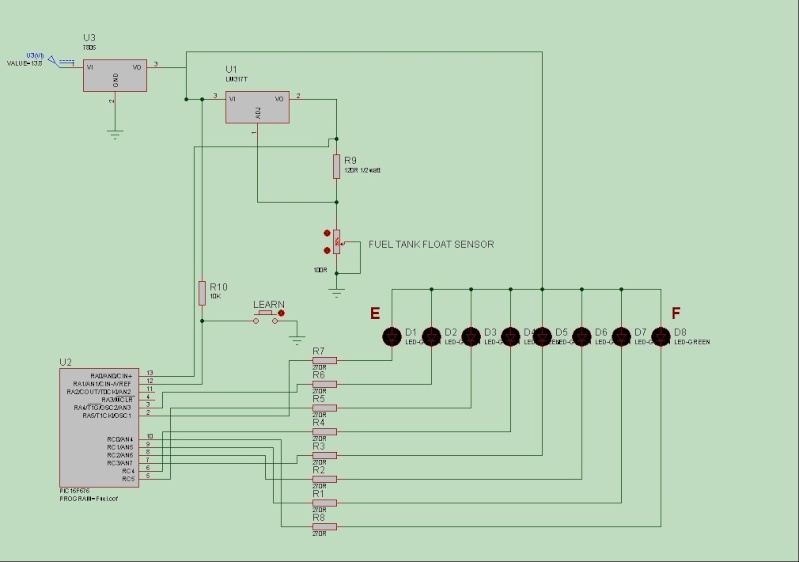
Circuit diagram.....
ASM code for the PIC 16F676.......
Code: Select all
; My Motorcycle fuel guage.
; The Honda has a 0-100 Ohm wirewound float sensor in post 2001 models, many pre '01 model owners have
; fitted the larger 19 litre tanks and dont have a fuel guage in the instrument cluster.
; I'm going to fit a VFR sensor to my 16 litre tank and have designed this simple circuit and code to display
; the fuel level on 8 leds, 1 led for each 2 litres of fuel.
; The circuit works as follows...
; Ign voltage is regulated by a LM7805 regulator, the output 5 volts is used for the PIC supply and also feed
; into a LM317T to limit the voltage and current being sent into the petrol tank, high voltage and current
; produces sparks and you definately dont want that!!
; The current is limited to 10mA and the voltage through the sensor changes from approx. 1.25V when empty to 2.5V
; when full this voltage is feed into an Analog to Digital convertor within the PIC and converted to a digital number.
; In the mainloop 10 readings are taken with a .5 second pause between each and then averaged up to compensate
; for fuel level movement during riding.
;
; The number of samples taken and delays are easily changed within the code if unstable readings due to movement
; are displayed.
;
; How to set-up for first use.
; Unfortunately you will have to completely drain the tank and have enough fuel available to fill it up.
; With an empty tank and the bike perfectly level, power on the unit with the button held down for at least a second,
; release the button for 1 sec and depress again for 1 sec. this sets the very empty setting, you can add fuel beforehand
; but not enough to raise the float.
; When the button is released the first led will flash slowly, measure out the fuel and add to the tank.
; When the level has stabilised and the float has moved, depress the button for 1 sec, the led will flash rapidly
; to indicate that the setting for that level has been set.
; Release the button and then the second led will flash slowly, add fuel and repeat the procedure until finished. the last
; led will not need to be set as anything above led no:7 will indicate a full tank.
ERRORLEVEL -302 ;remove message about using proper bank
processor 16F676
#include <p16F676.inc>
__config _CPD_OFF & _CP_OFF & _BODEN & _MCLRE_OFF & _PWRTE_ON & _WDT_OFF & _INTRC_OSC_NOCLKOUT
;**********************************************************************************************************
;***** Declaration of variable *****
cblock 0x20
Disp
temp
temp2
LED
NUMLEDS
THRESH1
THRESH2
THRESH3
THRESH4
THRESH5
THRESH6
THRESH7
THRESH8
PAUSEL
PAUSEH
ADCCount
ADC_Res0
ADC_Res1
AA0
AA1
AA2
BB0
BB1
REMB0
REMB1
Loopcount
endc
;**********************************************************************************************************
;***** Declaration of symbol equates *****
LEARNBTN equ 1 ; PORTA, pin RA1, has the "Learn" mode pushbutton
;**********************************************************************************************************
;***** Beginning of program memory structure *****
org 0x00
;**********************************************************************************************************
Start:
bsf STATUS,RP0 ; select Register Page 1
movlw 0x03
movwf TRISA ; Make PortA all ouput except RA0/1
clrf TRISC ; Make PortC all output
movlw 0x50 ; A2D Clock Fosc/16
movwf ADCON1
movlw 0x01 ; All Port A pins digital, except RA0
movwf ANSEL
bcf STATUS,RP0 ; address Register Page 0
movlw 0x07 ; Comparators off
movwf CMCON
movlw B'00000001'
movwf ADCON0 ; configure A2D for Channel 0 (RA0), Left justified, and turn on the A2D module
clrf ADRESH
movlw 0x7F ; Display off
movwf PORTC
bsf PORTA,4
bsf PORTA,5
movlw 0x08
movwf NUMLEDS
movlw 0x08
movwf LED
;**********************************************************************************************************
; Test to see if we should go into "Learn" mode.
; The PORTA RA1 pin has a pushbutton. Holding the button down at power on will cause the pin to go low
; and enter the learning routines.
checklearn
btfsc PORTA,LEARNBTN ; Check if the push button is being held down
goto LoadEE ; If not, then proceed
movlw high .1000 ; If so, then setup to debounce for 1 sec (1000 ms)
movwf PAUSEH
movlw low .1000
movwf PAUSEL
call Pausems
btfsc PORTA,LEARNBTN ; And check if the button is still being held down
goto LoadEE ; If not, then proceed
;**********************************************************************************************************
; Here we cycle through the LEDS 1 by one to learn the ADC threshold per 2 litres of fuel
; to the fuel tank. BUT the empty setting needs to be set first, no leds will be on for this
Startlearn
btfss PORTA,LEARNBTN ; Wait for the button to be released
goto $-1 ; Loop until button released
;**********************************************************************************************************
BlinkSlow
movlw high Hextoled
movwf PCLATH
movfw LED ; Get the LED number to be displayed
call Hextoled ; Convert it
movwf Disp
movwf temp2
comf Disp,1
movfw Disp
movwf PORTC ; Turn off the PORTC pins
movfw temp2 ; Ports only have 6 bits, get bits 7&8
andlw B'11000000' ; and use for PORTA.
movwf temp
rrf temp,1
rrf temp,1
comf temp,1
movfw temp
movwf PORTA
movlw high .500 ; Pause for 500 ms
movwf PAUSEH
movlw low .500
movwf PAUSEL
call Pausems
btfss PORTA,LEARNBTN ; Check if button pressed
goto Learn ; If so, proceed to learn it
movlw 0x7F ; Otherwise, turn off all leds
movwf PORTC
bsf PORTA,4
bsf PORTA,5
movlw high .500 ; Pause for 500 ms
movwf PAUSEH
movlw low .500
movwf PAUSEL
call Pausems
goto BlinkSlow ; Continue to flash the display
;**********************************************************************************************************
; Learn the actual ADC Reading for the gauge
Learn
movlw high .100 ; Debounce the pushbutton. Pause for 100 ms
movwf PAUSEH
movlw low .100
movwf PAUSEL
call Pausems
btfsc PORTA,LEARNBTN ; Check if button is still depressed
goto BlinkSlow ; If not, then resume flashing
BSF ADCON0,GO
BTFSC ADCON0,GO_DONE
GOTO $-1
MOVF ADRESH,W
movwf temp2
call WriteEE ; Store the ADC value into EEPROM
;**********************************************************************************************************
; Indicate that "Learning" has completed, by flashing the LEDs on/off quickly (once every 400 ms).
; We'll do this until the user releases the pushbutton.
BlinkFast
movlw high Hextoled
movwf PCLATH
movfw LED ; Get the LED number to be displayed
call Hextoled ; Convert it
movwf Disp
movwf temp2
comf Disp,1
movfw Disp
movwf PORTC ; Turn off the PORTC pins
movfw temp2 ; Ports only have 6 bits, get bits 7&8
andlw B'11000000' ; and use for PORTA.
movwf temp
rrf temp,1
rrf temp,1
comf temp,1
movfw temp
movwf PORTA
movlw high .200 ; Pause for 200 ms
movwf PAUSEH
movlw low .200
movwf PAUSEL
call Pausems
btfsc PORTA,LEARNBTN ; Check if button pressed
goto LearnNext ; If not, proceed to set up for learning the next threshold
movlw 0x7F ; Otherwise, turn off all leds
movwf PORTC
bsf PORTA,4
bsf PORTA,5
movlw high .200 ; Pause for 200 ms
movwf PAUSEH
movlw low .200
movwf PAUSEL
call Pausems
goto BlinkFast ; Then continue flashing the display quickly
;**********************************************************************************************************
; Now that we've "Learned" a setting, and the user has released the pushbutton, set up for learning
; the next led.
LearnNext
movlw high .100 ; Debounce the pushbutton. Pause for 100 ms
movwf PAUSEH
movlw low .100
movwf PAUSEL
call Pausems
btfss PORTA,LEARNBTN ; Check if button is still released
goto BlinkFast ; If not, then resume flashing
decf LED,F ; Decrement the led number to be learned
decfsz NUMLEDS,F ; Decrement the learning loop counter, and exit if zero
goto BlinkSlow ; Got it,start blinking the new led we need to learn
goto LoadEE ; Whewww, we're done
;**********************************************************************************************************
; Here we retrieve all previously "Learned" data from EEPROM.
LoadEE
call LEDCheck
movlw 0x08
movwf LED ; Re-hydrate all the RAM variables used to hold the thresholds
call ReadEE ; Working from LED 8 thru 1
movwf THRESH8
decf LED,F
call ReadEE
movwf THRESH7
decf LED,F
call ReadEE
movwf THRESH6
decf LED,F
call ReadEE
movwf THRESH5
decf LED,F
call ReadEE
movwf THRESH4
decf LED,F
call ReadEE
movwf THRESH3
decf LED,F
call ReadEE
movwf THRESH2
decf LED,F
call ReadEE
movwf THRESH1
;**********************************************************************************************************
; Due to the delays in the mainloop it can take a few seconds for the display to show anything, therefore
; we take a quick reading to start with.
firstreading
BSF ADCON0,GO
BTFSC ADCON0,GO_DONE
GOTO $-1
MOVF ADRESH,W
goto Gauge
;**********************************************************************************************************
MainLoop:
CLRF ADC_Res1
CLRF ADC_Res0
CLRF ADCCount
;**********************************************************************************************************
; Here we take 10 ADC readings with a 500ms delay between each sample, each sample is added to the previous
; one.
ADCLoop
MOVF ADCCount,W
SUBLW .9 ; Have we taken 10 samples?
BTFSS STATUS,C
GOTO ADCAverage ; Yes then now get the average
BSF ADCON0,GO
BTFSC ADCON0,GO_DONE
GOTO $-1
MOVF ADRESH,W
ADDWF ADC_Res0,F
BTFSC STATUS,C
INCFSZ ADC_Res1,F
INCF ADCCount,F
movlw high .500
movwf PAUSEH
movlw low .500
movwf PAUSEL
call Pausems
GOTO ADCLoop
;**********************************************************************************************************
; All 10 samples have been taken, grab the total and divide the result by 10.
ADCAverage
movfw ADC_Res0
movwf AA2
movfw ADC_Res1
movwf AA1
clrf AA0
clrf BB0
movlw .10
movwf BB1
Call DIV24x16
movfw AA2
;**********************************************************************************************************
; Here we take the average reading and compare it to the threshold values learned from the set-up routines.
; The average value is loaded into the W reg and the threshold value is subtracted, the Carry bit will be set
; if the threshold value is greater than the average reading.
Gauge
movwf temp2
movlw 0x08
movwf LED
movfw temp2
subwf THRESH8,W ; If W > THRESH, then C will be clear
btfsc STATUS,C ; If C is clear, then move on
goto EDisplay
decf LED,F ; Next led
movfw temp2
subwf THRESH7,W ; If W > THRESH, then C will be clear
btfsc STATUS,C ; If C is clear, then move on
goto FDisplay
decf LED,F ;
movfw temp2
subwf THRESH6,W ; If W > THRESH, then C will be clear
btfsc STATUS,C ; If C is clear, then move on
goto Display
decf LED,F ;
movfw temp2
subwf THRESH5,W ; If W > THRESH, then C will be clear
btfsc STATUS,C ; If C is clear, then move on
goto Display
decf LED,F ;
movfw temp2
subwf THRESH4,W ; If W > THRESH, then C will be clear
btfsc STATUS,C ; If C is clear, then move on
goto Display
decf LED,F ;
movfw temp2
subwf THRESH3,W ; If W > THRESH, then C will be clear
btfsc STATUS,C ; If C is clear, then move on
goto Display
decf LED,F ;
movfw temp2
subwf THRESH2,W ; If W > THRESH, then C will be clear
btfsc STATUS,C ; If C is clear, then move on
goto Display
decf LED,F ;
movfw temp2
subwf THRESH1,W ; If W > THRESH, then C will be clear
btfsc STATUS,C ; If C is clear, then move on
goto Display
decf LED,F ; then we must have a full tank!!!
goto Display
;**********************************************************************************************************
; Take the led number where the carry bit was set and lookup the result to switch the port bits on or off
Display
movlw high Hextoled
movwf PCLATH
movfw LED ; Get the number of LED's into the W register
call Hextoled ; Convert it
movwf Disp
movwf temp2
comf Disp,1
movfw Disp
movwf PORTC ; Turn off the PORTC pins to ground
movfw temp2 ; Ports only have 6 bits, get bits 7&8
andlw B'11000000' ; and use for PORTA.
movwf temp
rrf temp,1
rrf temp,1
comf temp,1
movfw temp
movwf PORTA
goto MainLoop
;**********************************************************************************************************
EDisplay ; Flashes all leds as tank is very empty!!
movlw .5
movwf temp
Empty
movlw 0x00 ; turn on all leds
movwf PORTC
bcf PORTA,4
bcf PORTA,5
movlw high .200 ; Pause for 200 ms
movwf PAUSEH
movlw low .200
movwf PAUSEL
call Pausems
movlw 0x7F ; turn off all leds
movwf PORTC
bsf PORTA,4
bsf PORTA,5
movlw high .200 ; Pause for 200 ms
movwf PAUSEH
movlw low .200
movwf PAUSEL
call Pausems
decfsz temp,f
goto Empty
goto MainLoop
;**********************************************************************************************************
FDisplay ; Flashes first led as warning
movlw .5
movwf temp
LowF
movlw 0x7F ; turn on first led
movwf PORTC
bsf PORTA,4
bcf PORTA,5
movlw high .500 ; Pause for 200 ms
movwf PAUSEH
movlw low .500
movwf PAUSEL
call Pausems
movlw 0x7F ; turn off all leds
movwf PORTC
bsf PORTA,4
bsf PORTA,5
movlw high .500 ; Pause for 200 ms
movwf PAUSEH
movlw low .500
movwf PAUSEL
call Pausems
decfsz temp,f
goto LowF
goto MainLoop
;**********************************************************************************************************
; Subroutine: Pausems
; Used to burn some CPU cycles doing nothing meaningful.
; This routine assumes a system clock frequency of 4 MHz.
; Inputs:
; PAUSEL - Low order byte of the number of milliseconds
; PAUSEH - High order byte of the number of milliseconds
; Temporary:
; LOOPCOUNT - Loop counter
; Output:
; None
Pausems
Loop1
movf PAUSEL,F ; Decrease PAUSEH and PAUSEL the necessary
btfsc STATUS,Z ; number of times and call subprogram Delay1ms
goto Dechi
call Delay1ms
decf PAUSEL,F
goto Loop1
Dechi
movf PAUSEH,F
btfsc STATUS,Z
goto Done
call Delay1ms
decf PAUSEH,F
decf PAUSEL,F
goto Loop1
Delay1ms ; Delay1ms produces a one millisecond delay
movlw .100 ; 100*10us=1ms
movwf Loopcount ; LOOPCOUNT<-100
Loop2
nop
nop
nop
nop
nop
nop
nop
decfsz Loopcount,F ; Time period necessary to execute loop Loop2
goto Loop2 ; equals 10us
Done
return ; Return to caller
;**********************************************************************************************************
;Divide a 24 bit number by a 16 bit number, resulting in a 16 bit number
;Inputs:
; Dividend - AA0:AA1:AA2 (0 - most significant!)
; Divisor - BB0:BB1
;Temporary:
; Counter - LOOPCOUNT
; Remainder- REMB0:REMB1
;Output:
; Quotient - AA0:AA1:AA2
;
DIV24x16
clrf REMB0
clrf REMB1
movlw .24
movwf Loopcount
LOOPU2416
rlf AA2,W ;shift dividend left to move next bit to remainder
rlf AA1,F
rlf AA0,F
rlf REMB1,F ;shift carry (next dividend bit) into remainder
rlf REMB0,F
rlf AA2,F ;finish shifting the dividend and save carry in AA2.0,
;since remainder can be 17 bit long in some cases
;(e.g. 0x800000/0xFFFF). This bit will also serve
;as the next result bit.
movf BB1,W ;substract divisor from 16-bit remainder
subwf REMB1,F
movf BB0,W
btfss STATUS,C
incfsz BB0,W
subwf REMB0,F
;here we also need to take into account the 17th bit of remainder, which
;is in AA2.0. If we don't have a borrow after subtracting from lower
;16 bits of remainder, then there is no borrow regardless of 17th bit
;value. But, if we have the borrow, then that will depend on 17th bit
;value. If it is 1, then no final borrow will occur. If it is 0, borrow
;will occur. These values match the borrow flag polarity.
skpnc ;if no borrow after 16 bit subtraction
bsf AA2,0 ;then there is no borrow in result. Overwrite
;AA2.0 with 1 to indicate no borrow.
;if borrow did occur, AA2.0 already
;holds the final borrow value (0-borrow,
;1-no borrow)
btfsc AA2,0 ;if no borrow after 17-bit subtraction
goto UOK46LL ;skip remainder restoration.
addwf REMB0,F ;restore higher byte of remainder.
;(w contains the value subtracted from it previously)
movf BB1,W ;restore lower byte of remainder
addwf REMB1,F
UOK46LL
decfsz Loopcount,F ;decrement counter
goto LOOPU2416 ;and repeat the loop if not zero.
return
;**********************************************************************************************************
;**********************************************************************************************************
; Subroutine: WriteEE
; Write a byte of data to EEPROM storage
; Inputs:
; LED - should be set to the LED number, which will be used as the EEPROM address
; W register - should contain the data to be stored
; Temporary:
; None
; Output:
; None
WriteEE
banksel EEDATA ; Select the bank of EEDATA
movwf EEDATA ; Data value to write
banksel LED
movf LED,W ; Use the LED number as the EEPROM address
banksel EEADR ; Select bank of EEADR
movwf EEADR ; Data memory address to write
banksel EECON1 ; Select bank of EECON1
bsf EECON1,WREN ; Enable writes
banksel EECON2 ; Select bank of EECON2
movlw 0x55
movwf EECON2 ; Write 55h
movlw 0xAA
movwf EECON2 ; Write AAh
banksel EECON1
bsf EECON1,WR ; Set WR bit to begin write
btfsc EECON1,WR ; Wait for write to finish
goto $-1 ; looping until it is
bcf EECON1,WREN ; Disable writes
banksel 0 ; Select bank 0 now that we're all done
return ; Return to caller
; Subroutine: ReadEE
; Read a byte of data to EEPROM storage
; Inputs:
; LED - should be set to the LED number, which will be used as the EEPROM address
; Temporary:
; None
; Output:
; W register - contains the EEPROM data byte that has been read
ReadEE
banksel 0
movf LED,W ; Get LED number into the W register
banksel EEADR ; Select bank of EEADR
movwf EEADR ; Data memory address to read
banksel EECON1 ; Select bank of EECON1
bsf EECON1,RD ; EE Read
banksel EEDATA ; Select bank of EEDATA
movf EEDATA,W ; Get EEDATA into W register
banksel 0 ; Select bank 0 now that we're all done
return ; return to caller
;**********************************************************************************************************
; Just cycle through the leds in bar mode up and down to confirm all are working.
LEDCheck
bcf PORTA,5
movlw high .200
movwf PAUSEH
movlw low .200
movwf PAUSEL
call Pausems
bcf PORTA,4
movlw high .200
movwf PAUSEH
movlw low .200
movwf PAUSEL
call Pausems
bcf PORTC,5
movlw high .200
movwf PAUSEH
movlw low .200
movwf PAUSEL
call Pausems
bcf PORTC,4
movlw high .200
movwf PAUSEH
movlw low .200
movwf PAUSEL
call Pausems
bcf PORTC,3
movlw high .200
movwf PAUSEH
movlw low .200
movwf PAUSEL
call Pausems
bcf PORTC,2
movlw high .200
movwf PAUSEH
movlw low .200
movwf PAUSEL
call Pausems
bcf PORTC,1
movlw high .200
movwf PAUSEH
movlw low .200
movwf PAUSEL
call Pausems
bcf PORTC,0
movlw high .250
movwf PAUSEH
movlw low .250
movwf PAUSEL
call Pausems
bsf PORTC,0
movlw high .200
movwf PAUSEH
movlw low .200
movwf PAUSEL
call Pausems
bsf PORTC,1
movlw high .200
movwf PAUSEH
movlw low .200
movwf PAUSEL
call Pausems
bsf PORTC,2
movlw high .200
movwf PAUSEH
movlw low .200
movwf PAUSEL
call Pausems
bsf PORTC,3
movlw high .200
movwf PAUSEH
movlw low .200
movwf PAUSEL
call Pausems
bsf PORTC,4
movlw high .200
movwf PAUSEH
movlw low .200
movwf PAUSEL
call Pausems
bsf PORTC,5
movlw high .200
movwf PAUSEH
movlw low .200
movwf PAUSEL
call Pausems
bsf PORTA,4
movlw high .200
movwf PAUSEH
movlw low .200
movwf PAUSEL
call Pausems
bsf PORTA,5
movlw high .750
movwf PAUSEH
movlw low .750
movwf PAUSEL
call Pausems
return
;**********************************************************************************************************
; Table used for the display routine to switch bits on or off
Hextoled
; table in bar mode
addwf PCL,F
retlw 0xFF ;B'11111111' ;Full
retlw 0xFE ;B'11111110'
retlw 0xFC ;B'11111100'
retlw 0xF8 ;B'11111000'
retlw 0xF0 ;B'11110000'
retlw 0xE0 ;B'11100000'
retlw 0xC0 ;B'11000000'
retlw 0x80 ;B'10000000'
retlw 0x00 ;B'00000000' ;Empty
;**********************************************************************************************************
end