
The workshop manual is a bit confusing to follow due to bad layout and makes it all sound a lot more complicated than it actually is. Hopefully this makes things a little more clear and easier to follow.
Notes:
a) It's a good idea to apply some lock-tight to all parts.
b) Be careful with the inner adjuster bolts as the castle type ends are easily broken.
c) Depending on what tools are used, it is not always possible to lock of the inner adjuster bolts while torquing up the outer castle lock nuts. In this case be aware that the inner adjuster may tighten up slightly off spec as the outer castle nut is torqued up. In this case you just have to do the best you can.
Start with getting everything installed hand tight.
1. Loosen off all threaded adjuster bolts that are fixed in the frame. This just allows some clearance space for the frame sliding over the engine.
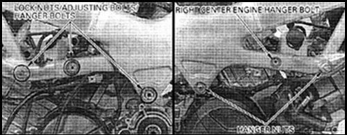
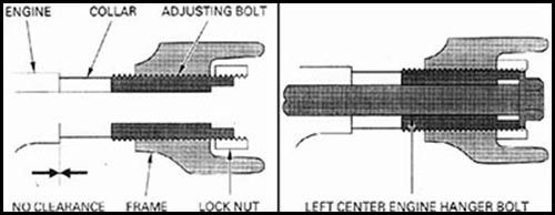
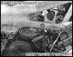
2. Loosely install the front and rear engine bolts (These are the long ones with the allen type head) from the left side through to the right, not forgetting to slip the front inner spacer collar in place between the engine and threaded adjuster bolt. Note the allen head is squared off to slide inside the threaded adjuster bolts. Loosely fit the outer castle type lock lock nuts over the top. These screw onto the ends (castle type) of the threaded adjuster bolts.
3. Loosely install the left centre hanger bolt through the threaded adjuster bolt in the frame, not forgetting the inner spacer collar. Then loosely fit the outer castle type lock lock nut over the top..
4. Loosely install the right side centre hanger bolt and front and rear hanger nuts.
That's everything hand tight and loosely fitted which assures that you have all the required parts. Also with everything being loose and free moving, this makes it simpler to get all threads started with a bit of wiggling and jiggling.
On to the tightening/torquing up sequence
Torque Values
Centre Engine Hanger Bolts = 39 N.m - 29 lb ft
Centre Adjusting Bolts (threaded part through frame) = 3 N.m - 2.2 lb ft
Outer Castle Type Lock Nuts = Indicated: 49 N.m - 36 lb ft and Actual 54 N.m - 40 lb ft.
Engine Hanger Nuts = 64 N.m - 47 lb ft.
1. Starting with the right centre engine hanger bolt, Torque to 39 N.m - 29 lb ft. This goes directly into the engine casting so go easy and don't over-tighten.
2. Move onto the left centre adjusting bolt. This is the threaded part that goes through the frame up against the spacer collar. Torque to 3 N.m - 2.2 lb ft. If possible holding the centre adjusting bolt move onto the outer castle type lock nut which is done in two stages. An indicated torque and and actual torque. Tighten to the Indicated Torque of 49 N.m - 36 lb ft. Once this is done, tighten the centre hanger bolt and Torque to 39 N.m - 29 lb ft. This also goes into the engine casing so go easy and don't over-tighten.
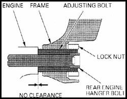
3. Move onto the rear adjusting bolt and from the left hand side If possible holding the centre adjusting bolt tighten the castle type lock nut which is done in two stages. An indicated torque and and actual torque. Tighten to the Indicated Torque of 49 N.m - 36 lb ft.
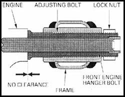
4. Move onto the front adjusting bolt. This is the threaded part that goes through the frame up against the spacer collar. Torque to 3 N.m - 2.2 lb ft. If possible holding the centre adjusting bolt move onto the outer castle type lock nut which is done in two stages. An indicated torque and and actual torque. Tighten to the Indicated Torque of 49 N.m - 36 lb ft.
5. Moving onto the right hand side tighten the rear engine hanger nut to a Torque of 64 N.m - 47 lb ft.
6. Tighten the front right engine hanger nut to a Torque of 64 N.m - 47 lb ft.
7. Now finally go around and tighten up to actual torques starting with the left centre castle type lock nut and Torque to 54 N.m - 40 lb ft. Then the left rear castle type lock nut and Torque to 54 N.m - 40 lb ft. Then the front left castle type lock nut and Torque to 54 N.m - 40 lb ft.
Done.
And for your convenience, a copy you can print out and get all greasy.
PDF Download Zip 194 kb
(:-})