I found this read interesting, from one of the links you supplied Carl

I know its about Cars, but isn't the VTR 6 cylinders from being a V8

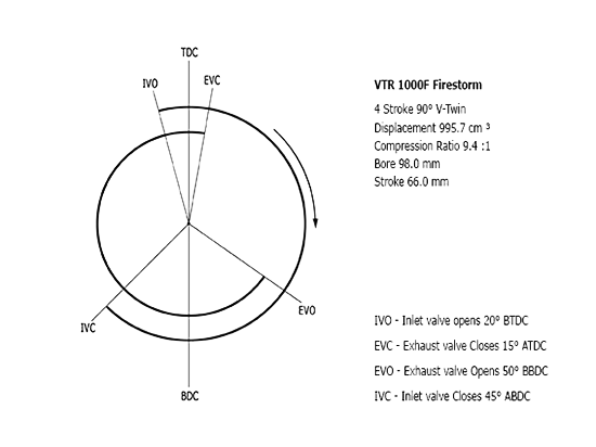
Cracking job of highlights the effects of lobe separation

From:
http://www.stevesnovasite.com/forums/sh ... hp?t=28638
In the early days of high- performance engine building, hot rodders discovered that when they squeezed the intake and the exhaust lobes closer together, the engine responded with more power. That experimentation continues to this day as engine builders struggle with the relationship between overlap and power.
Before we dive deeply into this subject, we should first define the term. Overlap is the number of crankshaft degrees that both the intake and exhaust valves are open as the cylinder transitions through the end of the exhaust stroke and into the intake stroke. The easiest way to understand overlap is by graphing the two lobes (see graph A) and examining the triangle created by the overlap of the intake opening (IO) and the exhaust closing (EC) points. This triangle is measured in degrees based on tappet checking height. This area is also referred to as the lobe separation angle—expressed as the spread in camshaft degrees between the intake centerline and the exhaust centerline.
This area is worth exploring because it is so complex. Let’s start with short-duration cams, which offer less overlap than long-duration cams even when they have the same lobe separation angle. Stated another way, a cam with more advertised duration is guaranteed to have more overlap than a cam with less advertised duration even with the same lobe separation angle. It’s also important to remember that overlap is ground into the camshaft when it is machined and cannot be changed without grinding a new camshaft unless you have a dual overhead cam engine with separate intake and exhaust cams.
Let’s look at a cam with an intake lobe centerline of 106 degrees after top dead center (ATDC) and an exhaust lobe with a 118-degree centerline before top dead center (BTDC). Adding the two values together and dividing by two equals 112 degrees. This is the lobe separation angle. While this number is useful, it doesn’t tell us much about the actual overlap between the intake and exhaust lobes. In order to calculate the actual overlap in crankshaft degrees, we need >> the intake opening (IO) and exhaust closing (EC) points. The SAE spec for advertised duration is 0.006 inch. Keep in mind that all cam companies do not use this spec. Let’s take a hydraulic-roller cam with an advertised duration of 276/282 degrees. The IO is 32 degrees BTDC and the EC is 27 degrees ATDC. Add these two values and we come up with 59 degrees of valve overlap.
Now let’s take a second, longer-duration cam with advertised duration figures of 294/300 degrees with an IO of 41 degrees BTDC and an EC of 36 degrees ATDC. We did the math and came up with a much larger figure of 77 degrees even though the lobe separation angle remains at 110 degrees. See how that works? This also illustrates why long-duration camshafts have such a lopey idle with very low idle vacuum. It’s not the duration itself, but the number of crankshaft degrees of engine rotation where both the intake and exhaust valves are open at the same time. At idle, there is plenty of time for residual exhaust gas in the combustion chamber to enter the intake manifold when the intake valve opens 41 degrees BTDC. This dilution of the intake manifold with exhaust gas is much like built-in exhaust gas recirculation (EGR) and is the culprit responsible for the unstable idle.
An unfortunate result of excessive overlap is reduced torque and soft throttle response at low engine speeds (e.g., below 3,000 rpm). So why build in all this overlap? The answer can be found when you look into the time that is compressed at high engine speed. At idle, there is plenty of time for the exhaust gas to move back up the intake tract and dilute the incoming charge. The intake air charge is also moving at a very slow speed. But buzz the engine to 6,000 rpm and there is precious little time for the exhaust gas to do anything except exit past the exhaust valve. Add the inertia of high-speed air entering the cylinder when the intake valve opens, and overlap is very useful for initiating that column of air into the cylinder. That 41 degrees BTDC intake opening point now works well to fill the cylinder with a big charge of air and fuel that now makes great power at 6,000 rpm. In effect, that early intake opening point gives the intake system a head start to fill the cylinder at high rpm when there is very little time. The result is more power at these higher engine speeds.
The difficulty with overlap is that the results change with different engine speeds. Since race engines tend to operate in relatively narrow rpm bands (e.g., 5,000 to 7,500 rpm), it’s easier to design a cam to work in this rpm band. A street engine is a greater challenge because it must operate through a rpm band of 5,000 rpm or more (1,000 to 6,000 rpm). The key to making overlap work is maximizing the power in the rpm band where you want it. Long overlap periods work best for high-rpm power. For the street, a long overlap period combined with long-duration profiles combine to kill low-speed torque. This makes for a soggy street engine at low engine speeds. Reducing overlap on a long-duration cam will often increase midrange torque at the expense of peak power, but if the average torque improves, that’s probably a change worth making.
The most important point in the four-stroke cycle is the intake closing point. While this is not part of overlap, the timing of intake opening and closing determines total duration. The intake closing point is a big determiner in where the engine makes power. A later intake closing point improves top-end power. Combine that with more overlap and you have a cam designed to make power at high rpm. However, it’s possible to decrease overlap by using a shorter-duration intake lobe and retard the intake centerline (which spreads the lobe separation angle) to improve midrange power.
We should also look at cams with a short duration and a wide lobe separation angle. All late-model Chevrolet engines use extremely wide lobe separation angles to improve idle quality. A late intake centerline combined with an early exhaust centerline and short-duration lobes creates very little overlap, yet the new LS1 and LS6 Gen III engines make great overall power without having to rely on large overlap periods. This is something to think about.
We would be remiss in not mentioning that many enthusiasts purchase a camshaft strictly on the basis of how it sounds. A cam with generous overlap creates that distinctive choppy idle that just sounds cool. There is a possibility that decreased overlap combined with an idealized intake closing point would create more power while producing a more stable (less lumpy) idle quality. This may not produce the idle sound most enthusiasts want to hear, but it is intriguing nonetheless.
There’s a ton more to learn about overlap and lobe separation angles than we can really get into in this short amount of space. It’s a relatively complex subject with many different conflicting requirements. But the more you learn about camshafts and how they operate, the more power you can make from your street engine.